Aristocraft Mallet Modifications & Repair page:
01/19/2008
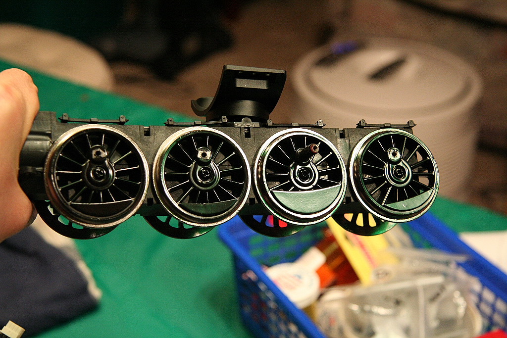
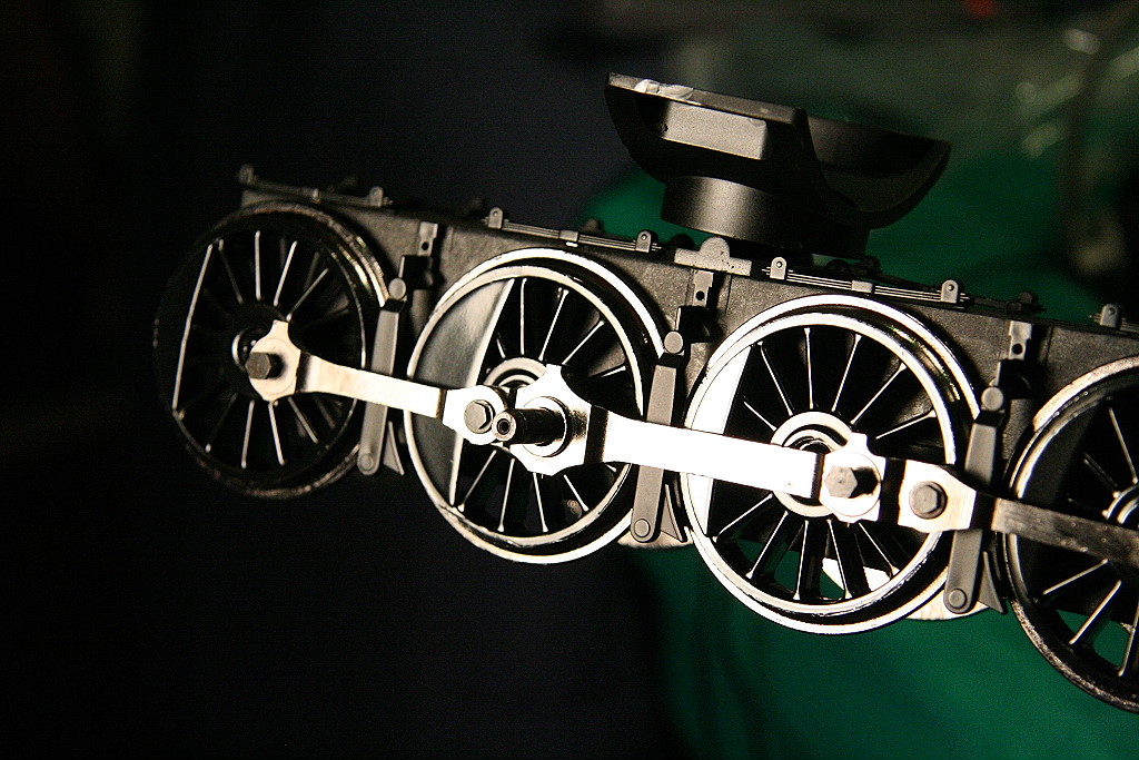
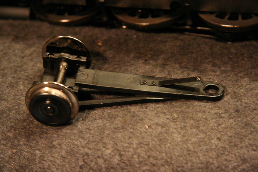
Drivers turning on axles and getting out quarter:
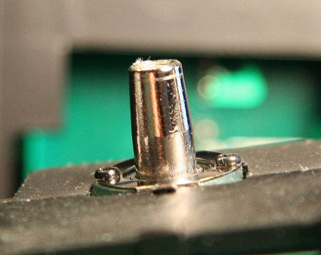
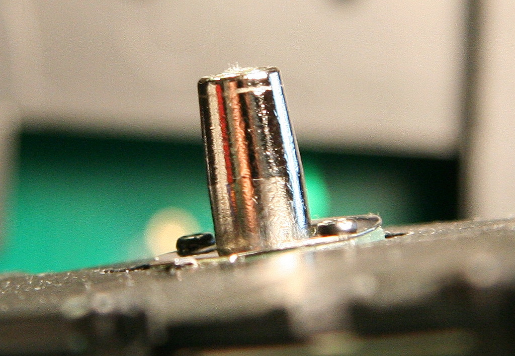
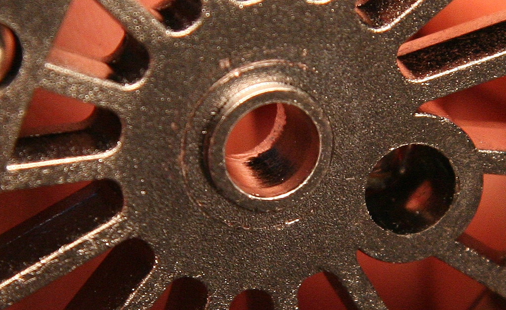
One issue common with these engines is that of the axles not fitting tight on the end of the axle and allowing them to get out of quarter and sometimes locking the drive-train. The main cause for them not fitting tightly is due to the inside taper surface of the driver (that mates against the axle taper surface) is tighter at the end near the outside portion of the driver than the axle is. If you clean the taper surfaces of both the axle and the driver with alcohol and then press and twist the driver on the axle end by hand, you will get this.... (photo below) A rub ring around the end of the axle which shows where the inside of the driver taper is making contact. In every single case where a driver could be turned on the axle, performing these steps showed the same rub ring. So the issue is the wheel casting die at the factory being out of spec relative to the axle casting.
|
|
|
||
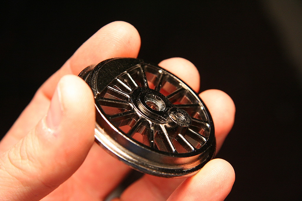
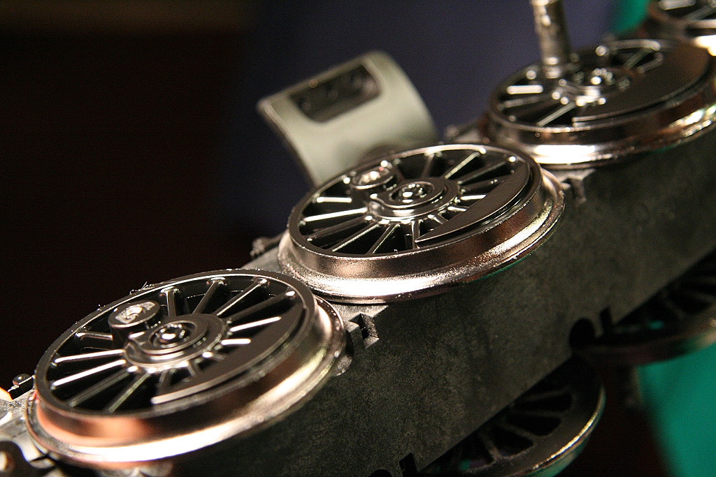
To resolve, it necessary to use a small fine modelers file to file out the inside outer end of the driver taper so all of the tapered surfaces of the inside of the driver will make contact with the axle taper surface. Pictured here the outside end of the inside taper has been filed down.
|
|
|
|
|
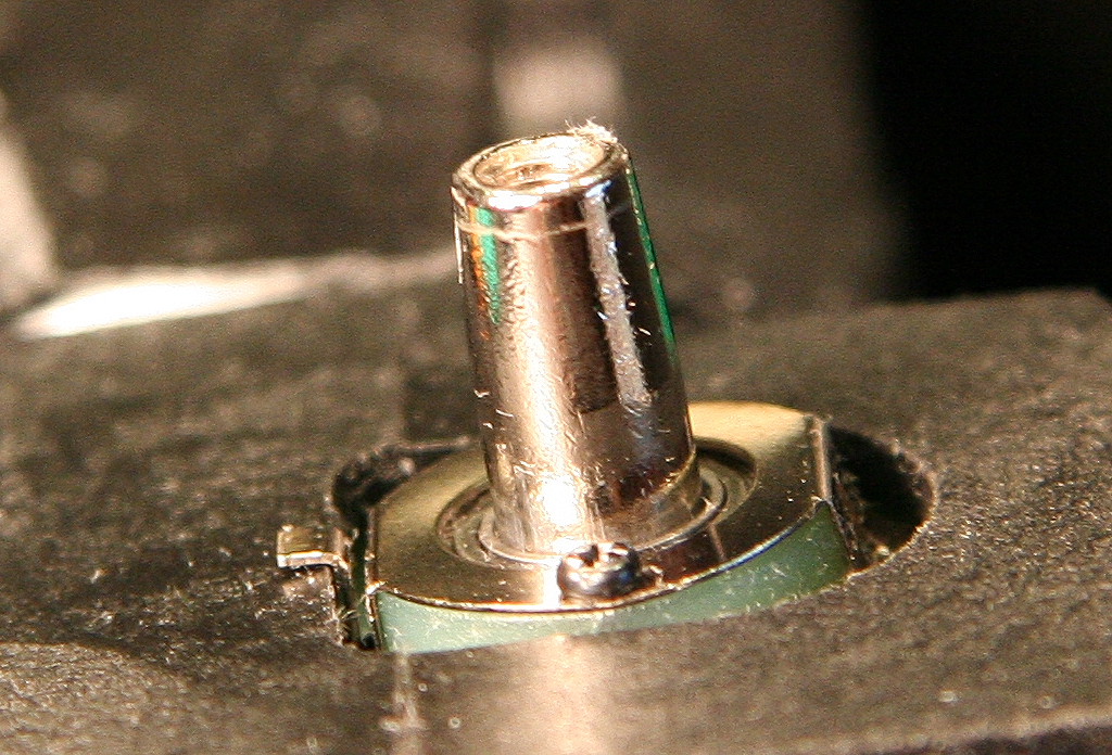
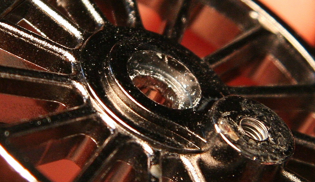
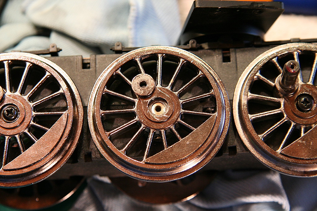
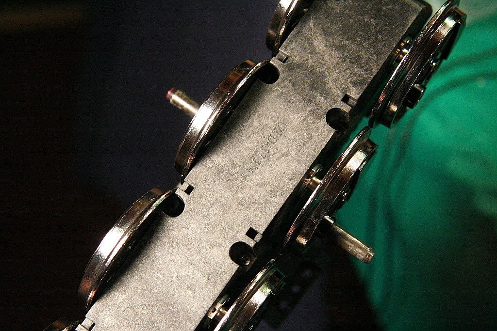
Another issue is the axle end can extend out too far from the inside of the driver such that tightening down on the end screw would result in the driver not securing tightly to the axle. The solution is to file down the end of the axle so it will be slightly recessed into the driver axle hole.
|
|
|||
After these two modifications are done, ensure again both surfaces are completely clean of oil and grease by cleaning with rubbing alcohol. Then take and push the driver down on the axle and twist the driver back and forth till they fit perfectly tight. (To assist you can use a rubbing compound.) (Note: for added insurance you can choose to add blue or red Loctite on the taper surfaces on final assembly. Just be aware that later removal of the driver will be very difficult.) Once the surfaces are properly mated adjust the driver's quartering by placing the rods temporarily back over the driver pin holes. Once the driver is in position, reinstall the axle screw and star washer.
The combination of these two modifications results in a very secure driver on the axle.
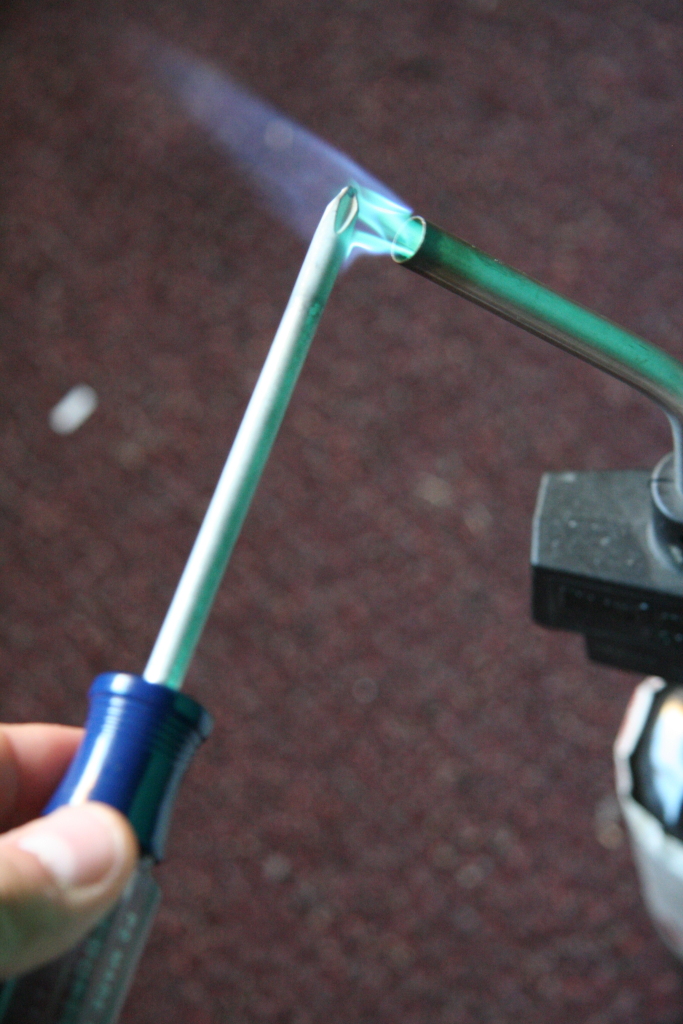
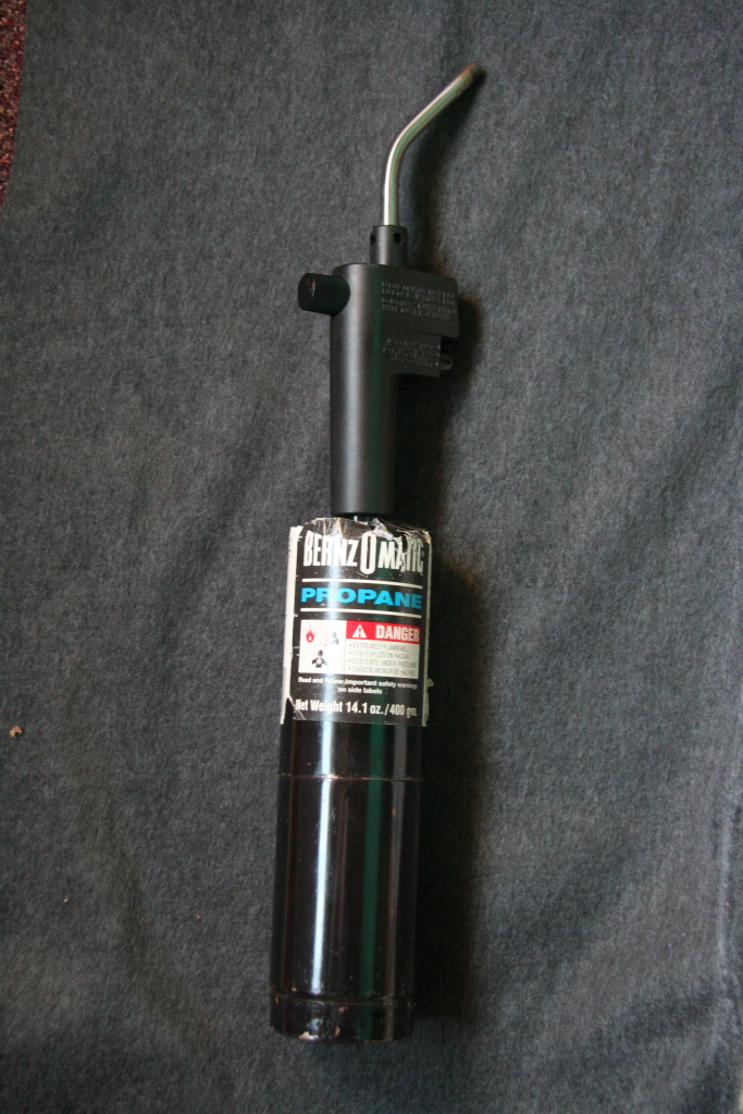
Note: In order to get the axle screws out of the axles without them snapping off, use a blow torch to heat the tip of a Philips head screwdriver very hot then use on the screw-head. When you fit the screw driver tip in the screw head, the heat will transfer from the screw driver head to the screw and will soften the Loctite (used to secure the screw) and allow the screw to back out. Be careful and don't apply too much torque as the screws snap very easily. You may need to repeat the heat and unscrew process more than once per axle as there is a short window of time the Loctite is softened as the heat transfers from the screw tip into the screw and then cools back down as it's fully transmitted through the entire axle and driver. Also note that this process of heating the screwdriver tip will eventually ruin the screwdriver tip so use one with a lifetime warranty so you can exchange it out. If you have to do a number of drivers it's best to have a number of extra screwdrivers on-hand.
|
|
|||
_________________________________________________________________________________
09/06/2008
Drivers out of quarter fix: rework connecting rod holes: (*CHECK THIS ON ALL NEW ENGINES BEFORE RUNNING FOR THE FIRST TIME!*)
Another issue with virtually every Mallet I've seen is individual drivers being out of quarter causing driveline binds. This leads to erratic running performance and eventually the strain can break a driver loose on the axle causing it to spin. The fix can include trying to re-adjust the driver on the axle but this can involve a bit of time and effort to get re-secured back on the axle properly... and even still you are still likely to have a slight bit of resistance. One fairly quick and easy way to address this problem is to simply oval out the connecting rod holes with a Dremel) allow more play/range of motion in the driver pins. Because the drivers are all powered via internal drive gear blocks and flywheels, opening up the rod holes does not negatively impact the running characteristics in any way.
Here is an example video of a new Mallet with driveline binding because of out of quarter drivers. In this video I'm trying to start the engine by slowly applying track power... it should start moving slowly but it goes from stopped to moving at a good clip quickly.
=============================================================================================
Note: if the video skips, right click on the link and select "save target as" and save it to your local drive, then play it.
Select the version / quality you want to download:
 - Video #1 - 3:48 mins - Demo of a Mallet with drive-line
binding
- Video #1 - 3:48 mins - Demo of a Mallet with drive-line
binding
- 87MB/3000kbs - 30MB/1000kbs - 11MB/400kbs
==============================================================================================
A more refined way to tell if your drive line has binding is to tip the engine on it's side and run the drivers around slowly and stop in many positions per revolution. Check and wiggle the each section of the rod assembly, you should have some play in the rods in all positions and in all sections. If you don't you may need to open the holes up a bit. Another test is with the engine still on it's side and watch the rods as they complete each revolution. If you see certain joints push up this is evidence of binding from an out of quarter driver which means one or more drivers are loose on the axle and/or installed out of quarter from the factory.
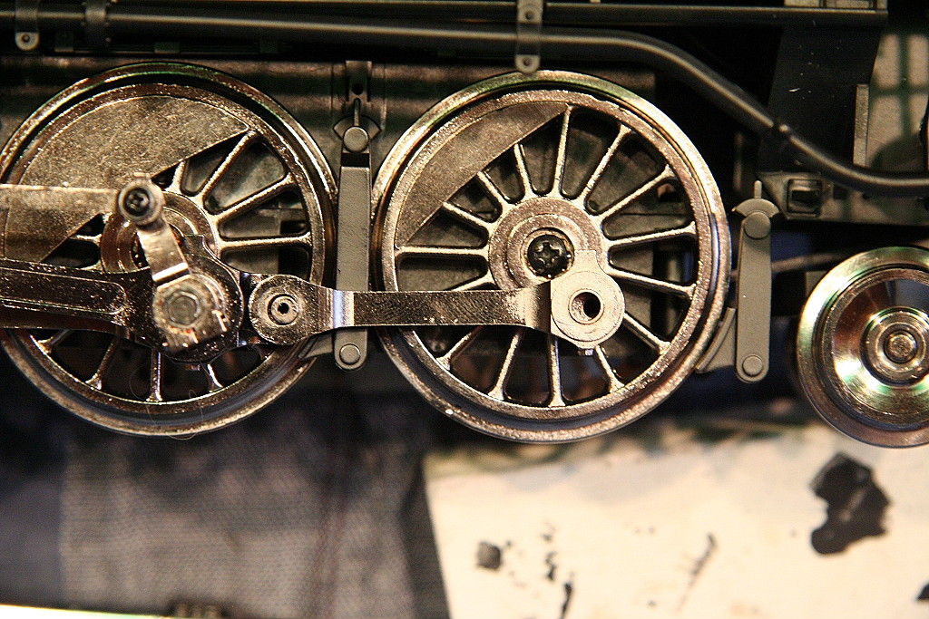
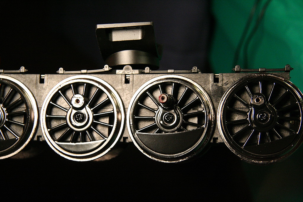
Here is an example of how far out of quarter this driver is from the factory on this new engine. If not fixed, this would eventually lead to a driver spinning on the axle.
|
||||
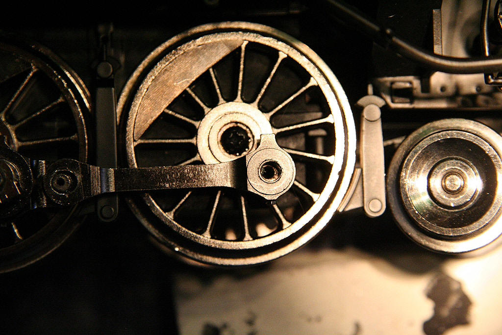
With some ovaling out of the hole you can allow for the driver being out of position (in both positions) as it completes a full revolution:
|
|
|||
After rework, you usually can't see the additional rod ovaling in most cases and if it is visible you have to really look close to see it. There are a number of dremel bits available that work well for this type of work. This is much faster way to eliminate driver quartering binding than trying to reposition each driver in the precise correct position. If you do have a driver that far out of quarter it will be best to readjust it.
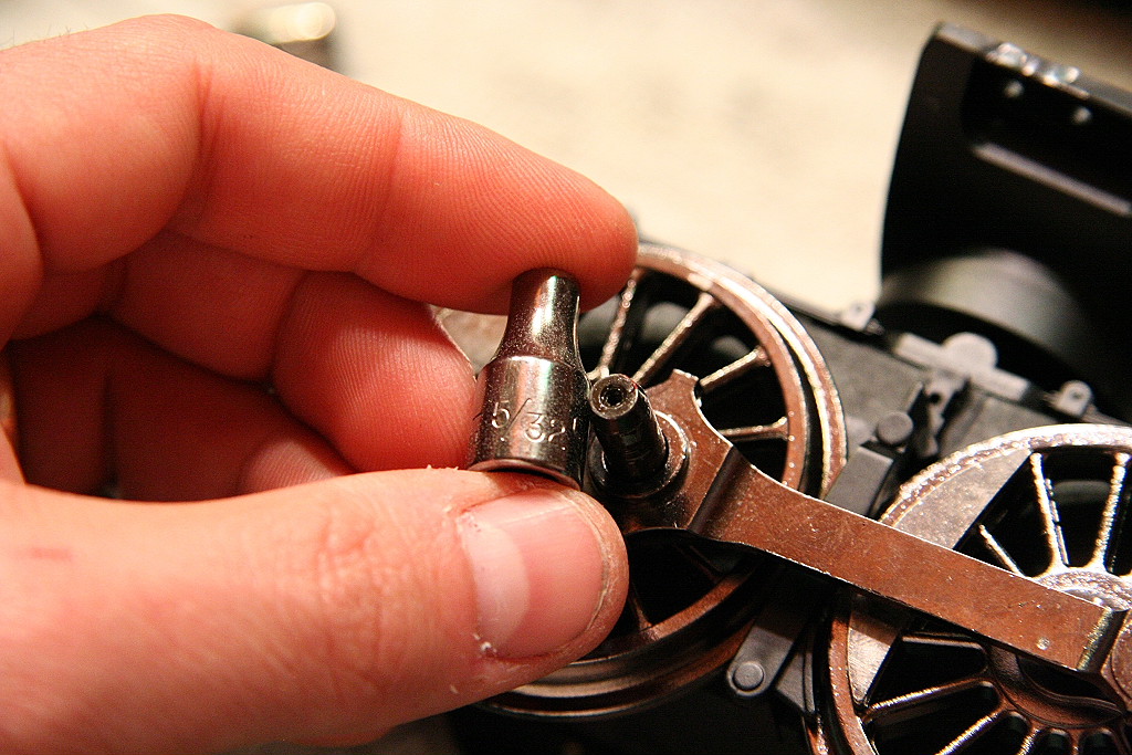
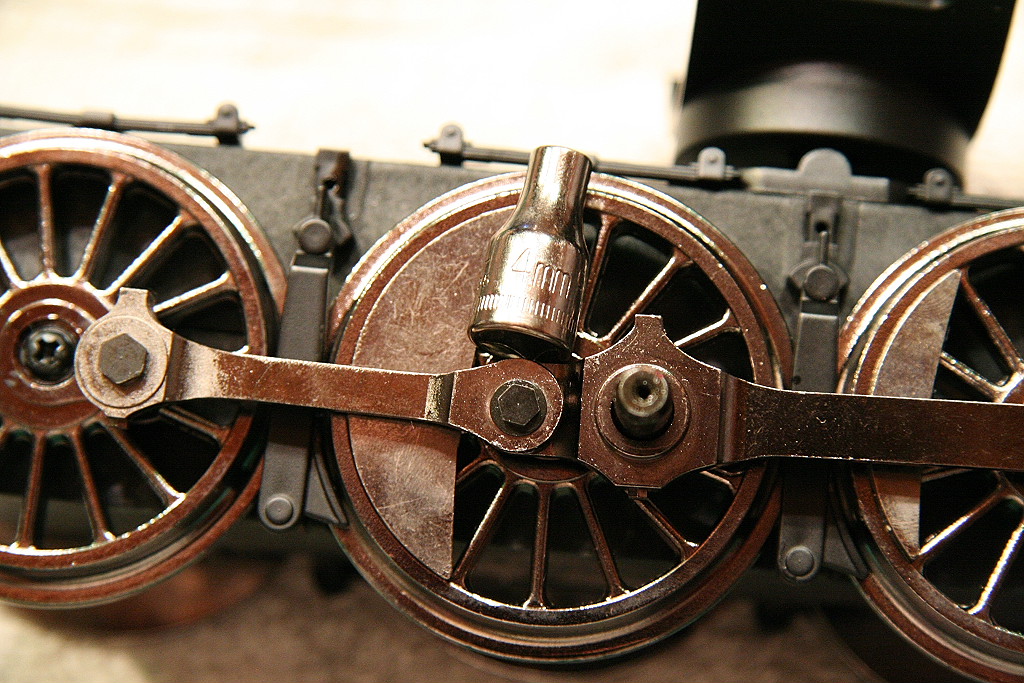
Note: Here are the socket sizes need to remove the rod screws:
|
|
|
||
** Caution: When trying to remove the rod screws, (especially the smaller 4mm screw head) if you encounter too much resistance they may have Loctite on the threads. Use a soldering iron to heat the screw head up to soften the Loctite, then try to remove. You can break the screw-head off in the driver/rod if you aren't careful. **
**** NOTE: Running an engine that has driveline binding to "Break it in" WILL NOT properly resolve the issue and will if anything lead to one or more drivers spun loose on the axle ends. The only way the binding can go away is for you to correctly adjust the driver by loosening the screw (see other write-up sections for more info) or by ovaling the rod holes as I've noted. If the driver gives and turns on the axle as a result of the driveline binding, you will most likely have a problem at some point with that driver coming completely loose on the axle and locking the entire drive train. So in other words, if you have binding, DON'T RUN IT. Fix it first!!!
In many cases, the owner may not realize that they have driveline binds from the very beginning. I highly recommend you watch the video and take the time to thoroughly check both engine sets for any binding before running. Don't assume it doesn't have binding just because it looks like it runs ok. ****
Once you eliminate all binding from the rods it will be much less likely to have a driver spin on the axle in the future.
_________________________________________________________________________________
09/06/2008
Rod pins impacting main rod as engine runs: (unexplained 'clinking' sound)
This is an issue I've found when running the Mallet was that the motor block has too much side to side play on the axles. This results in the engine making a metal 'clinking' sound as it runs around the track because the #2 or #3 driver rod pin (don't remember which) could actually impact the main rod as the engine ran. This is a big risk as if it fully catches it would likely lock the drive train, cause a driver to spin on the axle or something to break. I'm not certain if this would be an issue on the Mikado but it is something to consider.
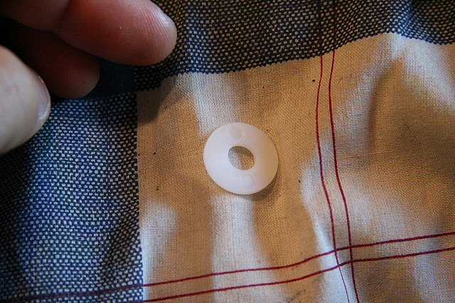
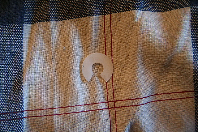
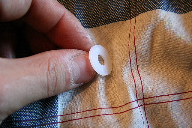
The way to fix this is to add a 5/16" Nylon washer (can be purchased from Home Depot) to each of the #1 drivers on each engine set. (Pictured is a 1/4" washer)
|
|
|
|
|
Here is an example of them installed on the MTH Big Boy:
|
|
|||
_________________________________________________________________________________
01/19/2008
Connecting rod pins screwed in crooked:
I found this on a couple of engines I was trying to perfect the quartering on. While seemingly very minor, they can increase the resistance at certain points in the revolution of the driver that can lead to the pin coming loose or cause/accentuate minor binding. Fortunately, backing them out and re-screwing back in straight up and down can correct the problem.
|
|
|
||
_________________________________________________________________________________
01/19/2008
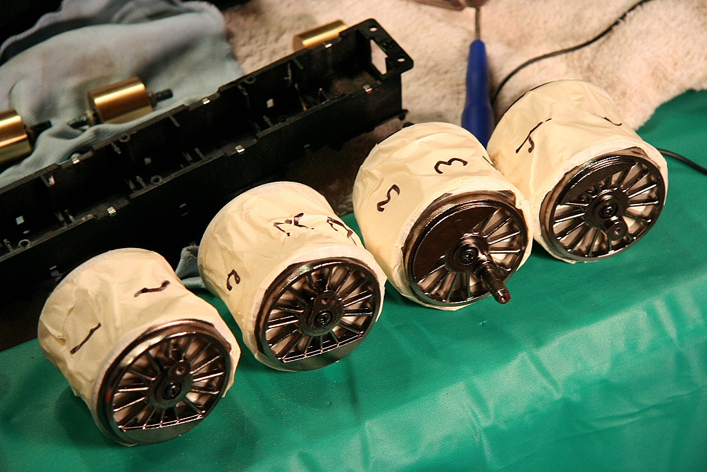
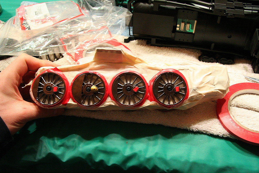
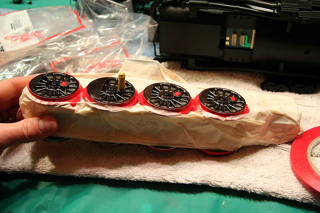
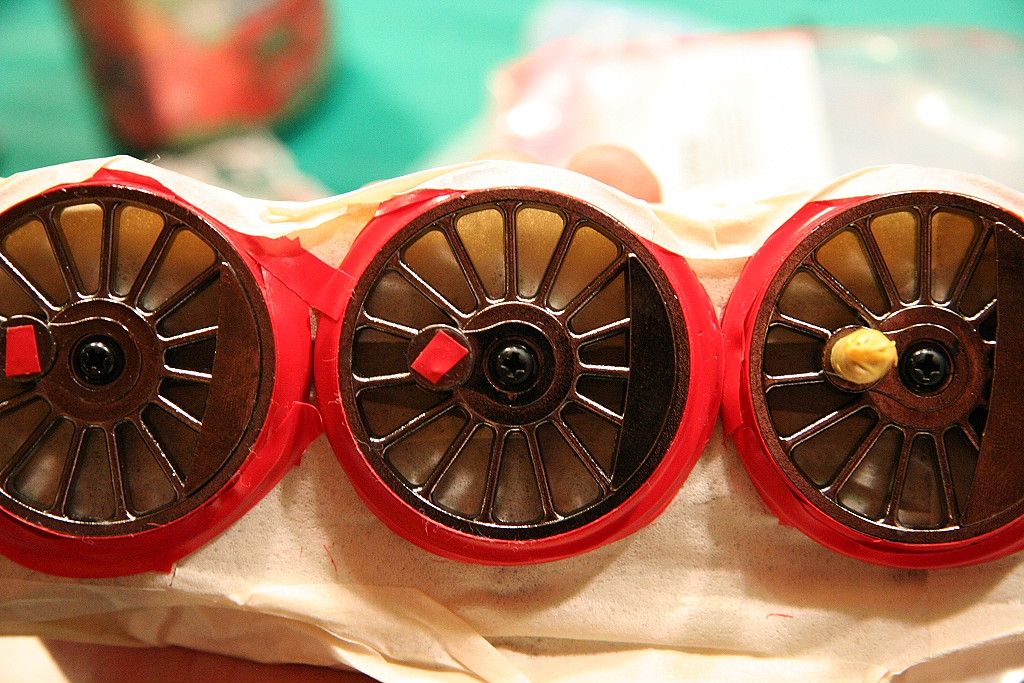
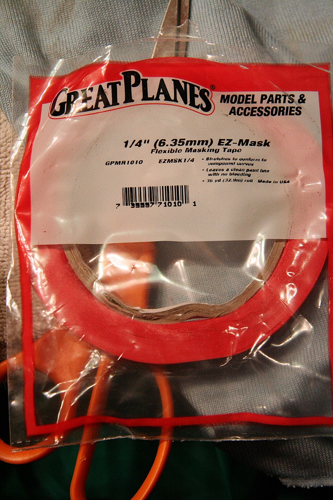
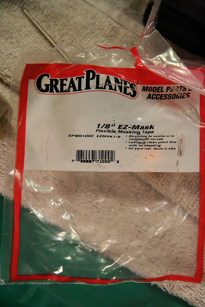
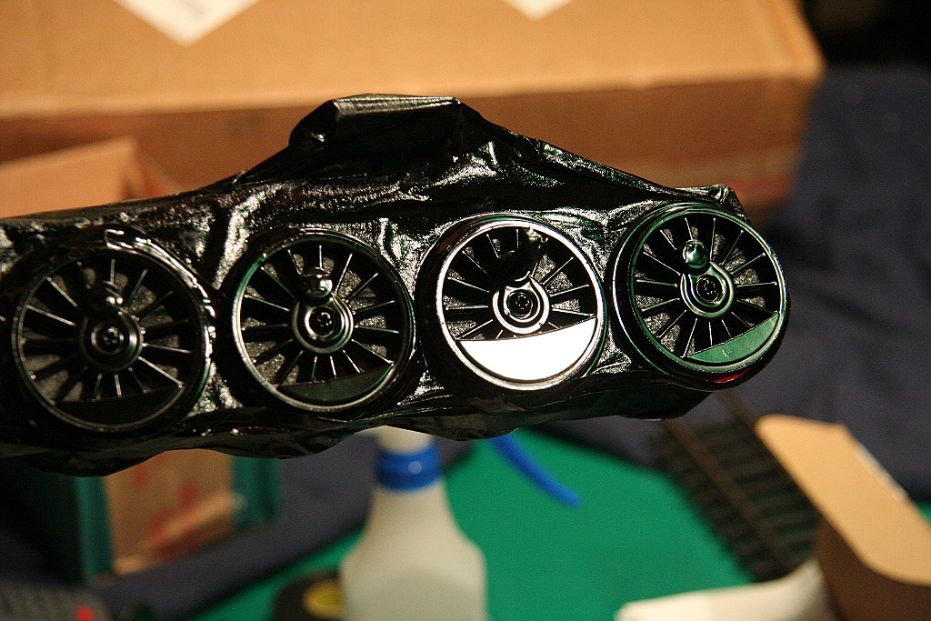
Painting the drivers:
To get an overall better look you might choose to paint your drivers black. To get as precise a job as possible, it's best to disassemble each motor block, remove each axle set and masked the surfaces you don't want painted. Be sure to mark the direction and location number on the bottom of each gear box. It is also a good idea to draw a center line down the side of each flywheel to note it's original orientation, direction and order. This is critical in order to maintain the quartering!
The paint used in these photos was Krylon Fusion - Satin Black.
First, here are the socket sizes need to remove the rod screws:
|
|
|
||
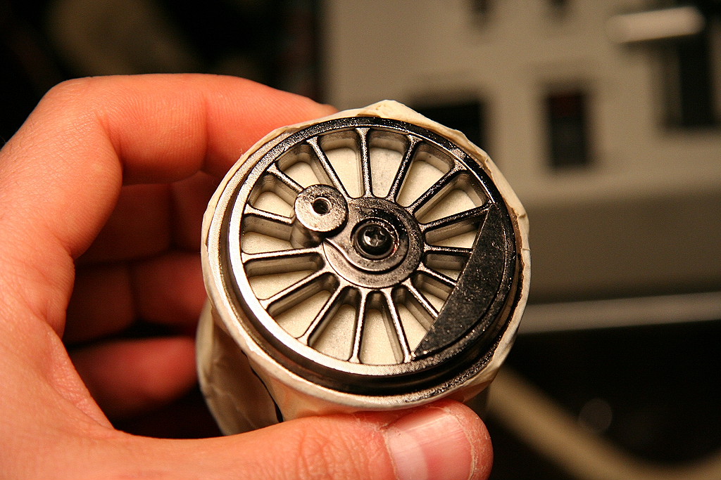
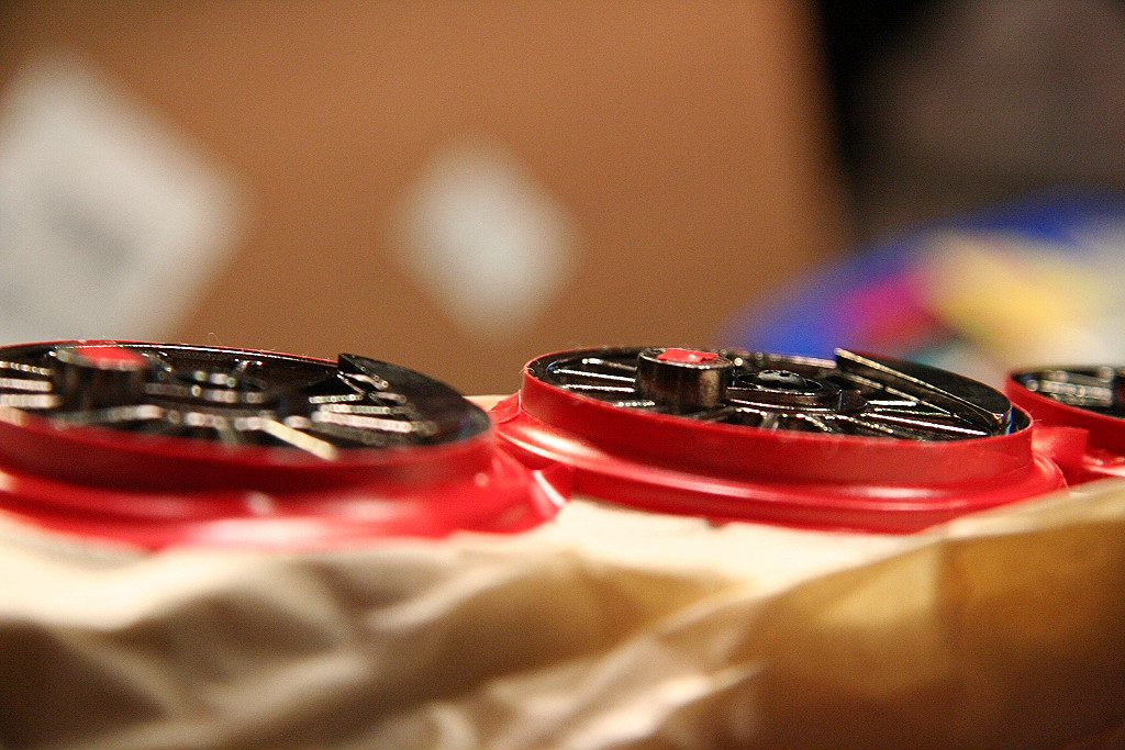
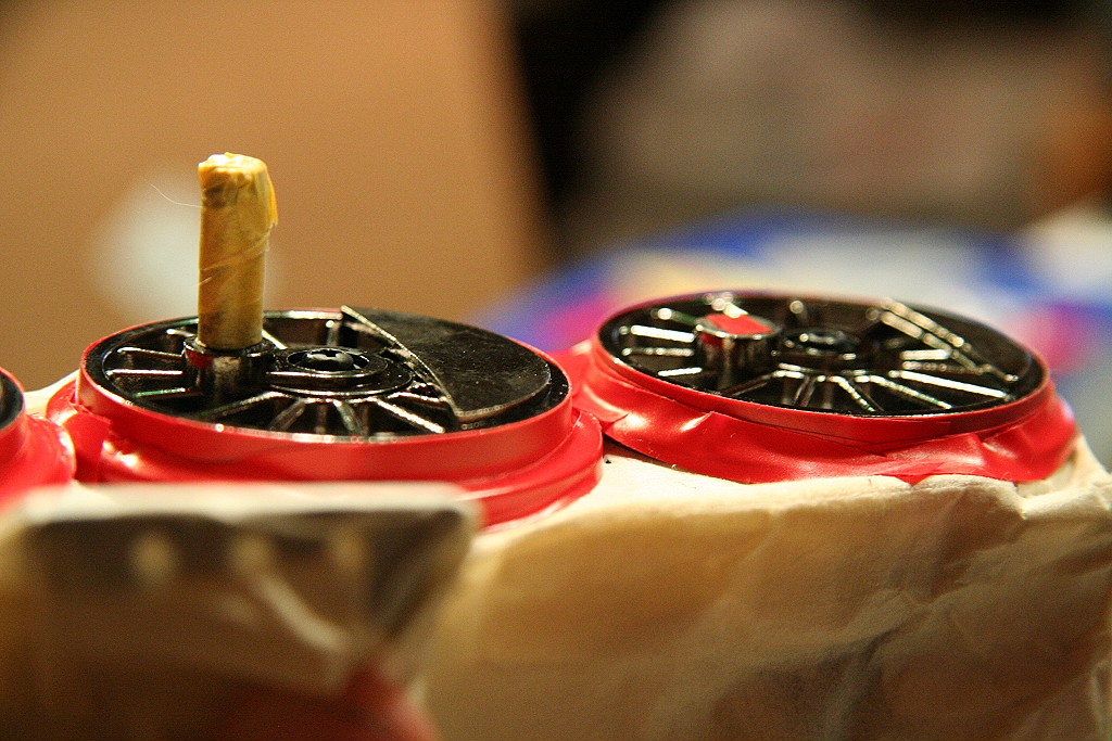
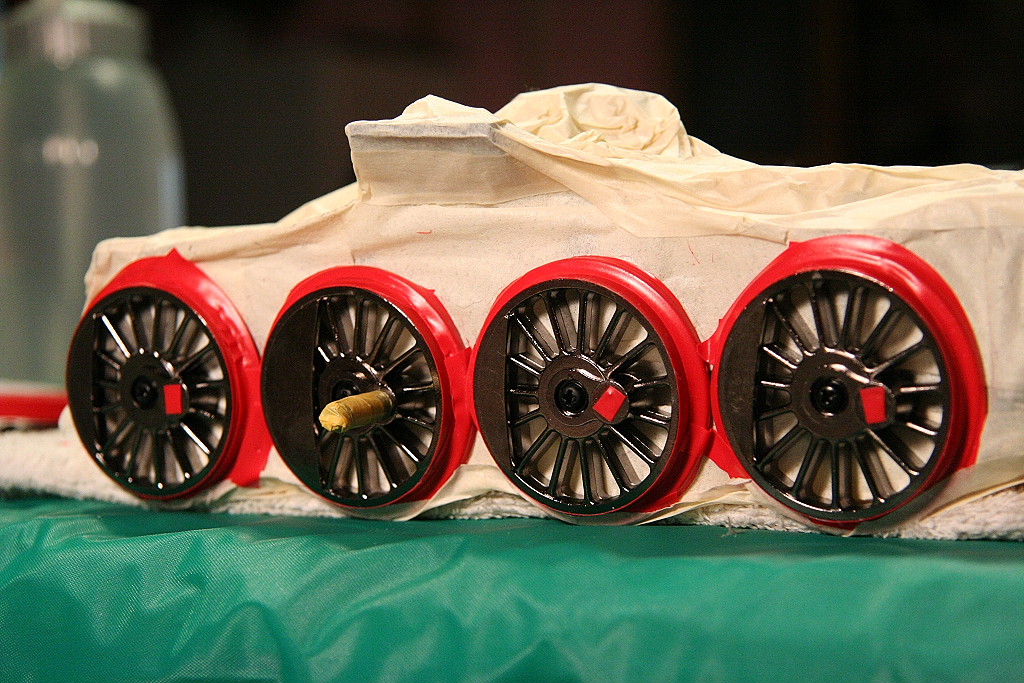
Drivers partially masked.
|
|
|
|
|
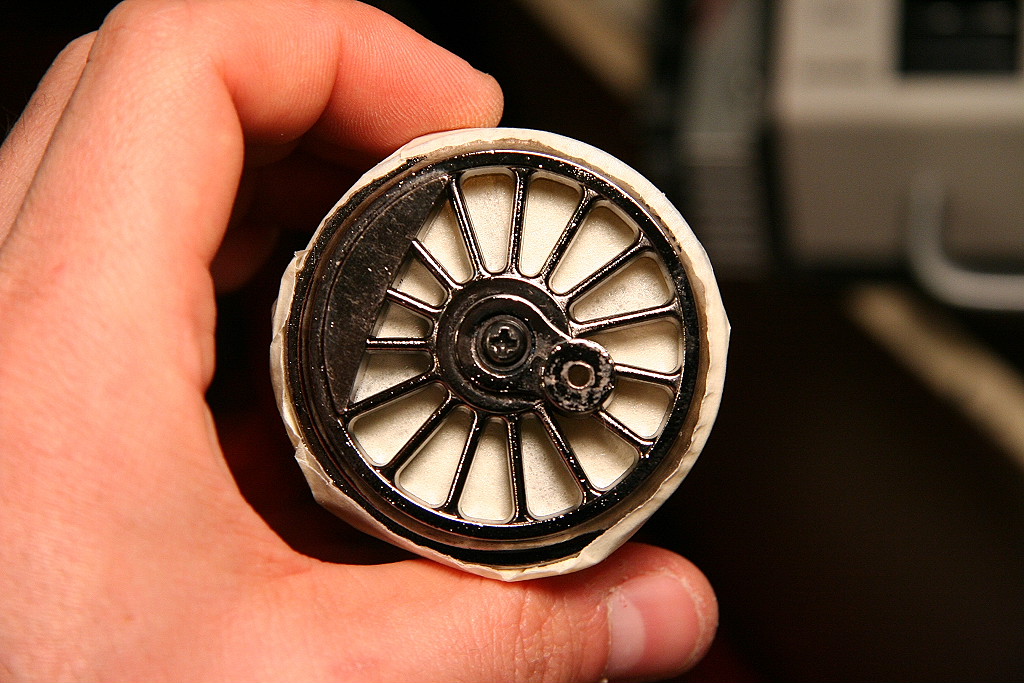
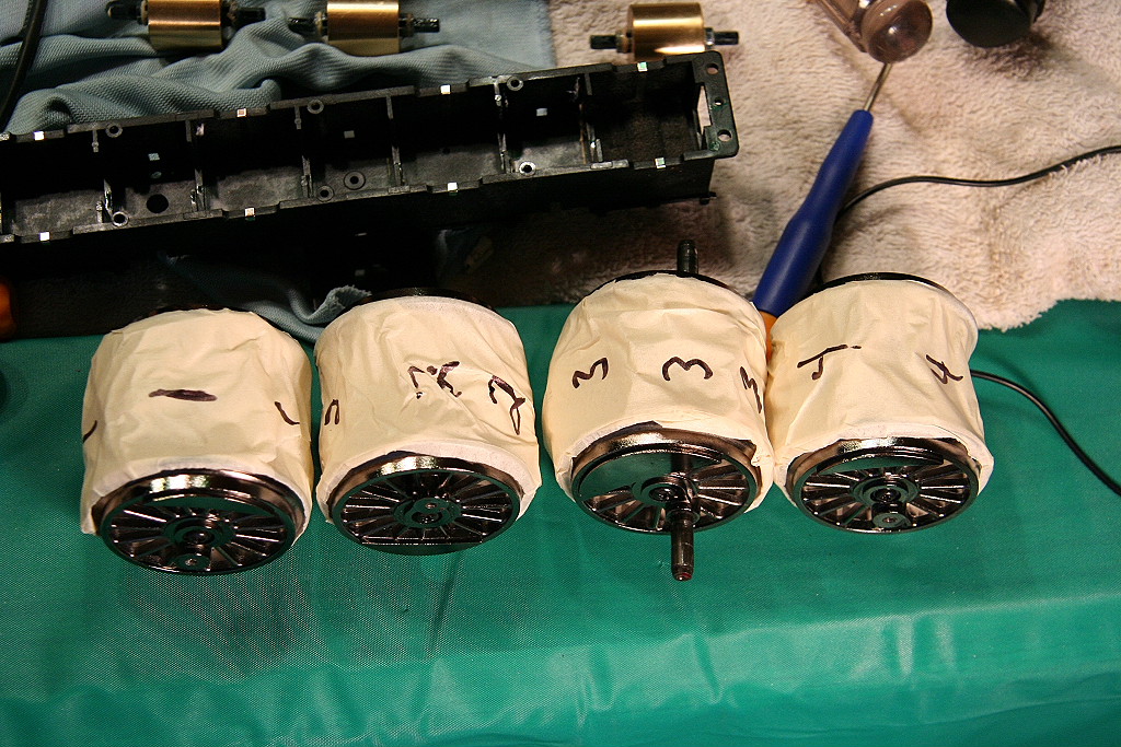
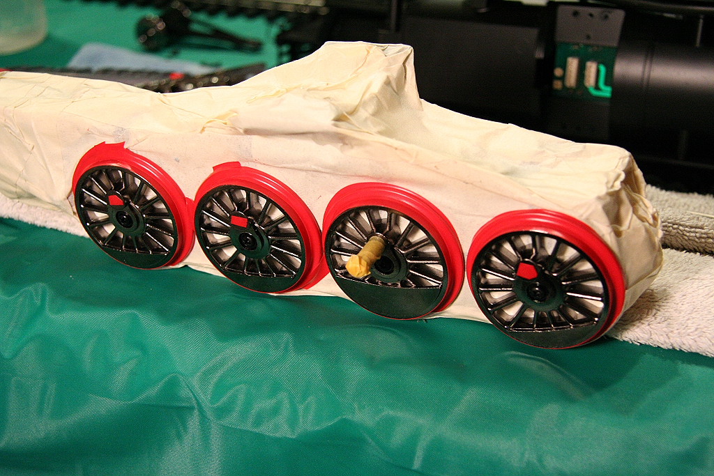
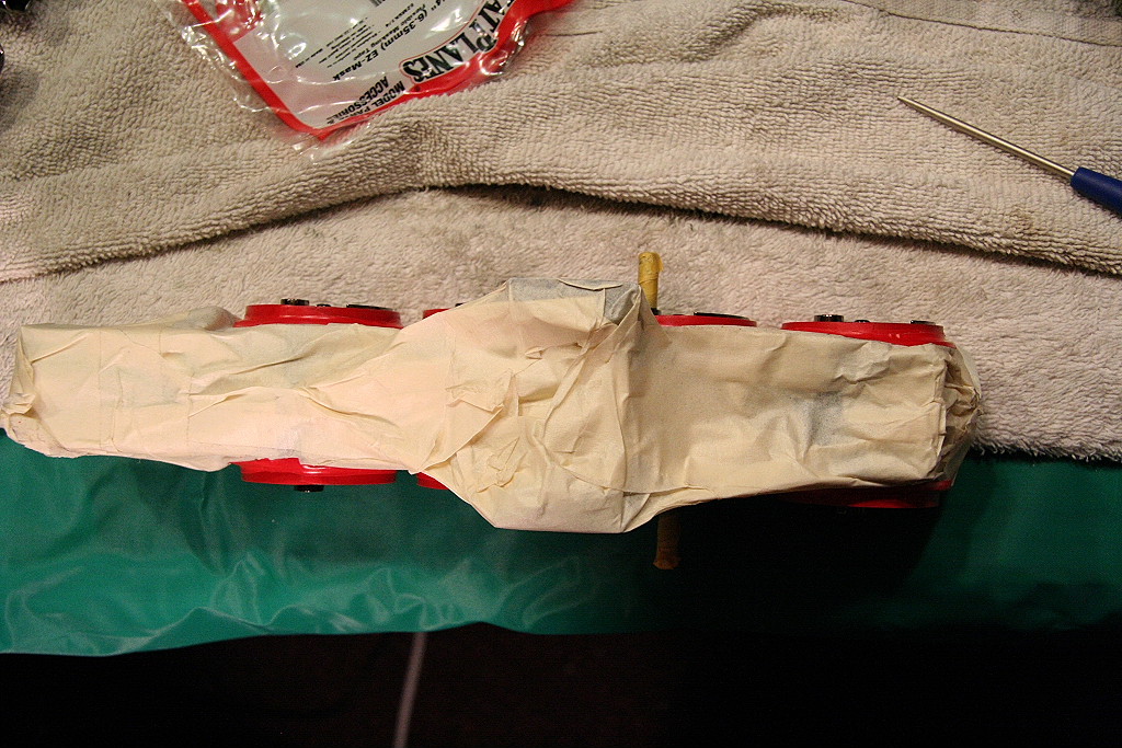
Drivers completely masked. (Note in these photos, it documents my original method of not removing the gearboxes from the block.)
|
|
|
|
|
|
|
|
|
|
|
|||
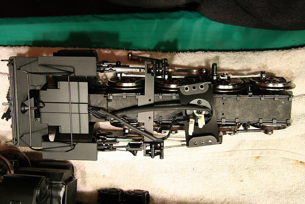
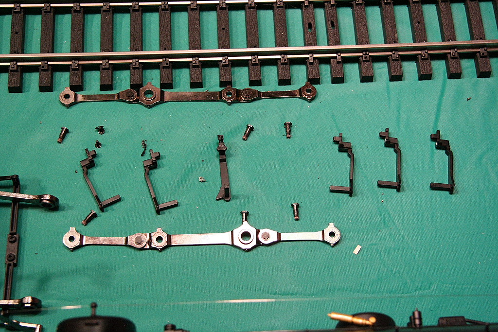
Images of the disassembled pieces of the Mallet motor block and other images:
|
|
|
|
|
|
|
|
|
|
||||
Images of the just painted drivers:
|
|
|
|
|
|
|
|
|
|
|
|||
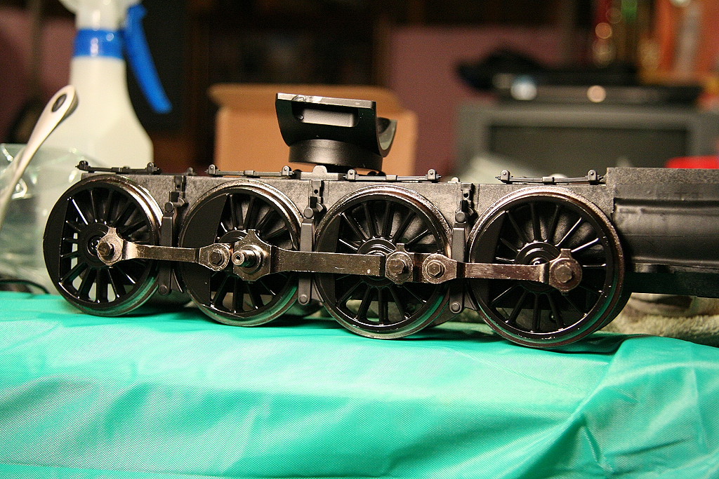
Final end result reassembled and back on the engine:
|
|
|
|
|
|
|
|
|
|||||
_________________________________________________________________________________
01/19/2008
Defective motor:
One issue that can also come up is where one engine set runs noticeably slower than the other which leads to one set pushing/dragging the other. After eliminating the possibility that it is out of quarter/loose drivers, crooked rod pins or a wiring problem, it could be the motor itself. See the videos below.
(Right-click and save-as the video before you play and it will run smoother.)
Select the version / quality you want to download:
- Video #1 - 1:45 mins
- 26MB/2100kbs - 13MB/1000kbs - 2MB/150kbs
- Video #2 - 1:31 mins
- 23MB/2100kbs - 11MB/1000kbs - 2MB/150kbs
_________________________________________________________________________________
01/19/2008
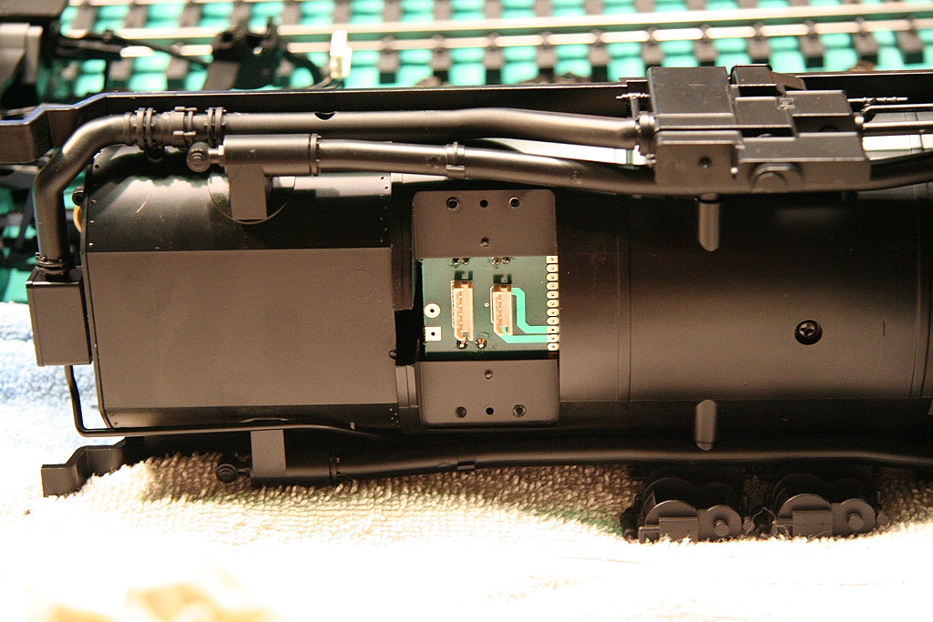
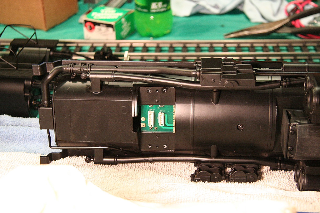
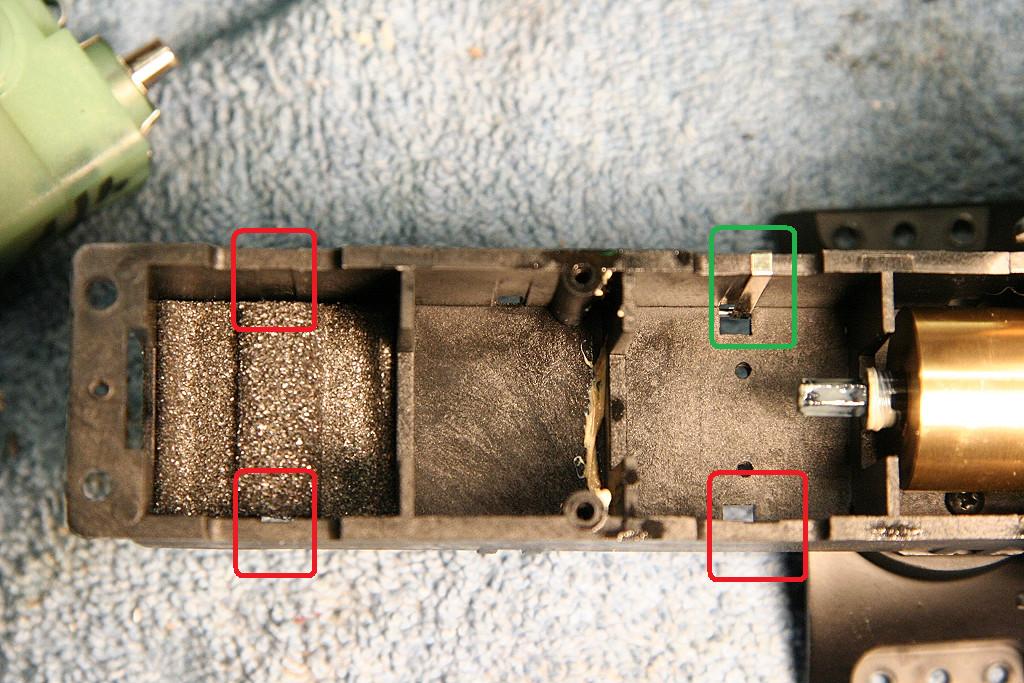
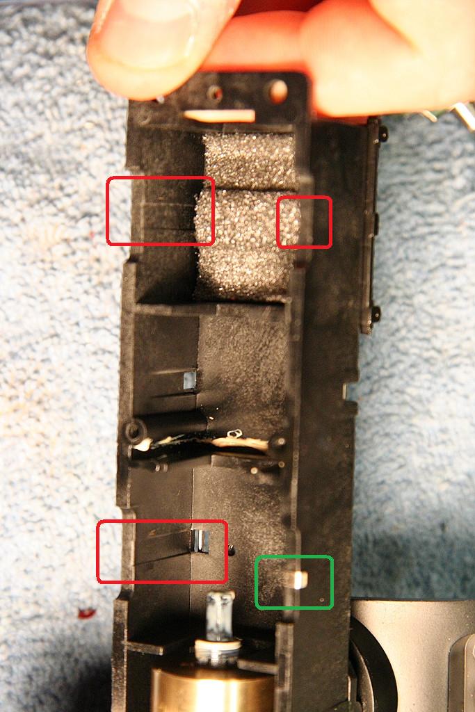
Power pickup problems from some drivers: (missing power transmission strips)
On 3 axles (out of 48) I found that no power was being picked up from the driver. The cause ended up being the power transfer strips that ran down the inside of the motor block was missing on all three axles. Aristocraft was good enough to provide replacement strips to me.
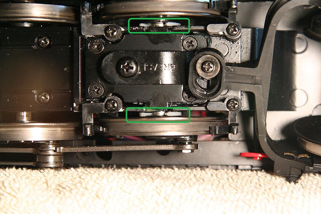
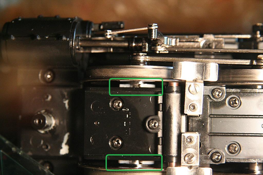
You can see in the second photo that the power transfer strip is there in the top right location, but in the other three, they are missing. (Below and the top and bottom in the gear box area on the left.)
|
|
|
||||
_________________________________________________________________________________
01/19/2008
Power pickup problems from some drivers: (power pickup ball missing on axle to ball power pickup)
On one axle I found that power was not being transferred to the engine. It turned out to be the very small ball bearing that is installed on the bottom side axle hole (through the side of the gearbox) was missing.
These are a 2mm ball and can be ordered from: http://www.precisionballs.com/ "Standard Commercial balls" - 316 Stainless steel.
__________________________________________________________________________________
05/31/2009
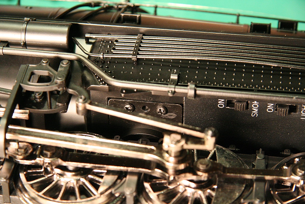
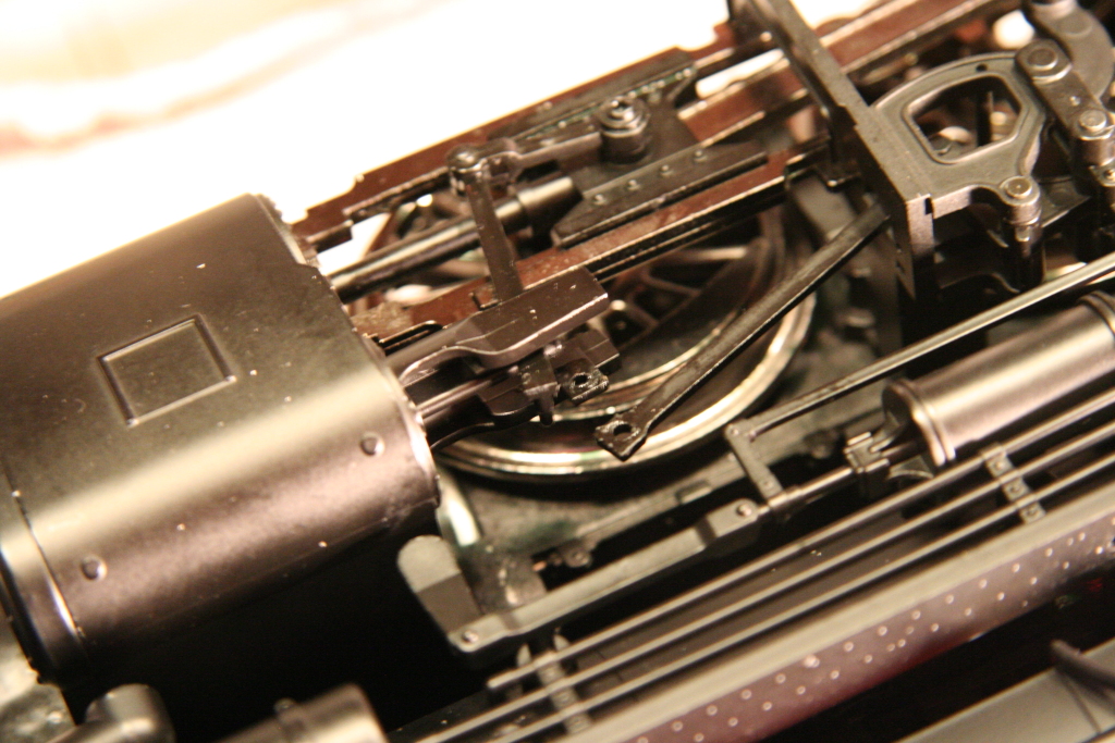
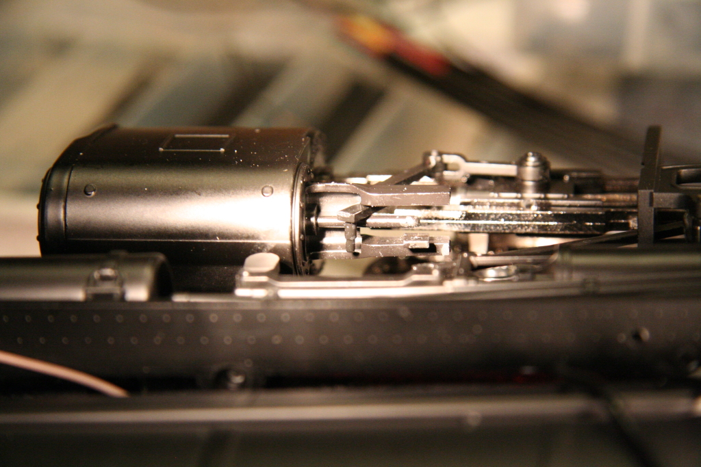
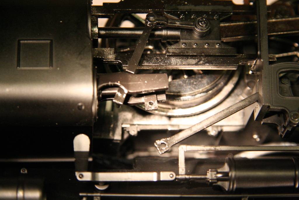
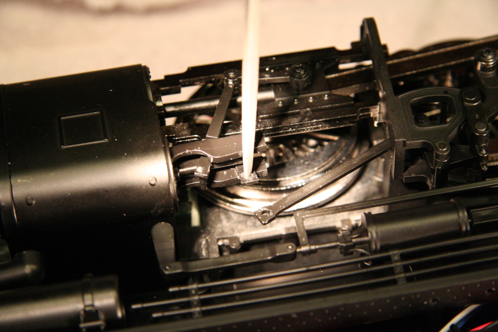
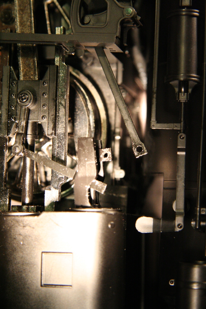
Recurring plastic "creeking" noise while running - (Twice per revolution of the wheels)
You may hear this on your engine and can't seem to figure out where it's coming from. The most likely place is from the crosshead screw connection on one of the crossheads.
Here is the connection with the screw removed and the connector taken off. Just lubricate this point and reassemble.
|
||||
To help you identify which one is making the noise, with the engine running put your finger on the screw at the center of the crosshead. If it's making the noise you will feel the vibration in your finger tip. If you don't feel it, try another one.
If it's not one of the crosshead screws, another possibility could be the upper rocking point connection for the actuator arm that the crosshead moves. I have used a file to enlarge the hole the pin fits in to allow for more play. This location is most likely not the one causing noise.
|
|
|
|
|
_________________________________________________________________________________
03/13/2011
Drive train (Gearbox) failures
Once your engine gets a good amount of run time you may encounter the issue where either a gearbox fails or the entire drive-train fails to operate.
The failure will be either one of two things(or both):
Plastic axle gear or plastic worm gear strips in one or more of the gearboxes
Hex shaped hole on an individual gearbox's worm gear will strip out
If the plastic axle/worm gear strips out that drive-wheel will no longer spin with the rest of the wheels and will allow that driver set to get out of quarter with the rest of the drivers. This will cause the entire drive train to lock-up.
If the Hex shaped hole on a worm gear strips out that gearbox and all others driven off of it will no longer turn. If it's the first gear box (attached to the motor) then the entire drive train will fail to operate. If it's a second, third or later, then that gearbox's wheel set and all others after it will fail to turn causing them to get out of quarter with the gearbox wheels that are still operational.
In either case you will need to to either replace the gearbox or send the drive-train in to Aristocraft for replacement. Aristocraft engines have a 5 year warranty and will replace it for free if still under warranty.
Example of failure of Mikado: (same drive-train as Mallet)
_________________________________________________________________________________
11/21/2010
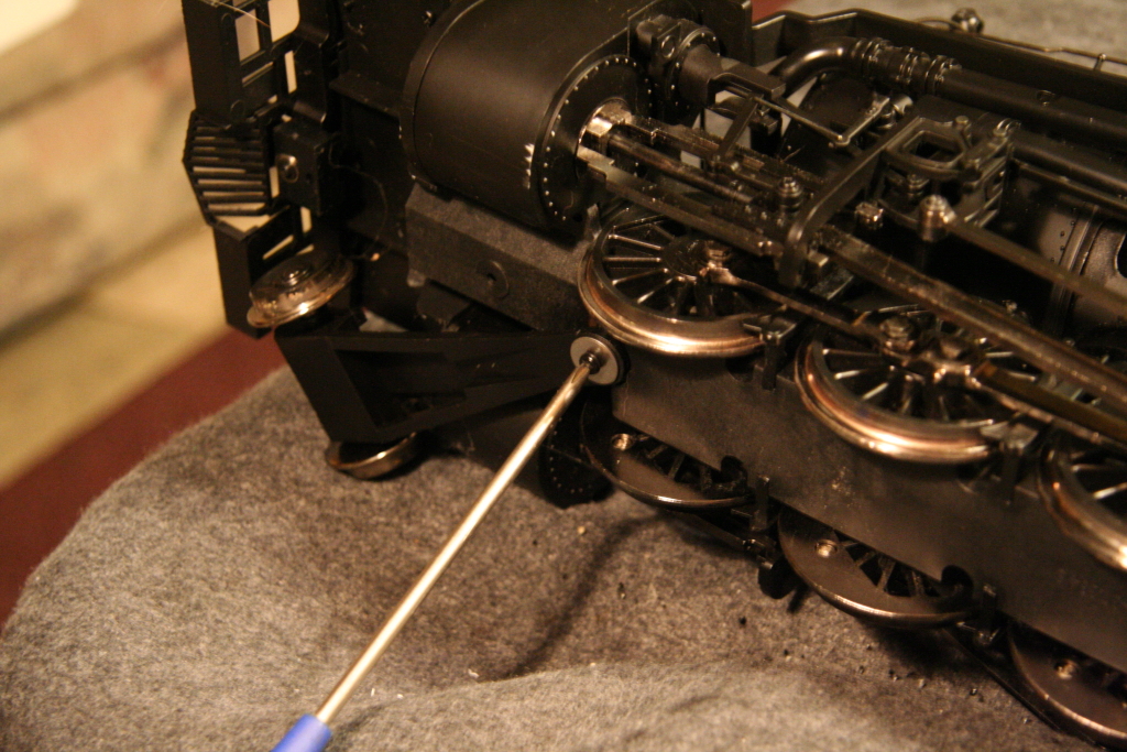
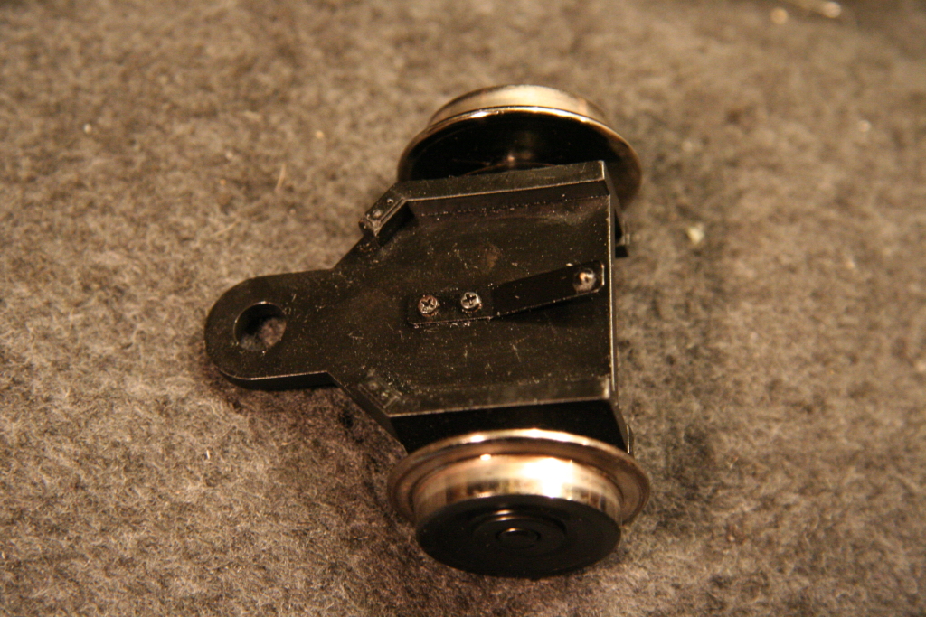
Lead truck on engine derailing / Increase downward pressure on lead truck
If you run a Mallet through a switch backwards (with it switched the other direction the lead truck will likely derail (even if the switch points are spring-loaded to allow for such an event). The truck derails because there is insufficient downward pressure from the frame above to keep in from raising off the track due to the fact the weight transfer spring is pointed at the rear where it has no real leverage to apply pressure.
|
||||
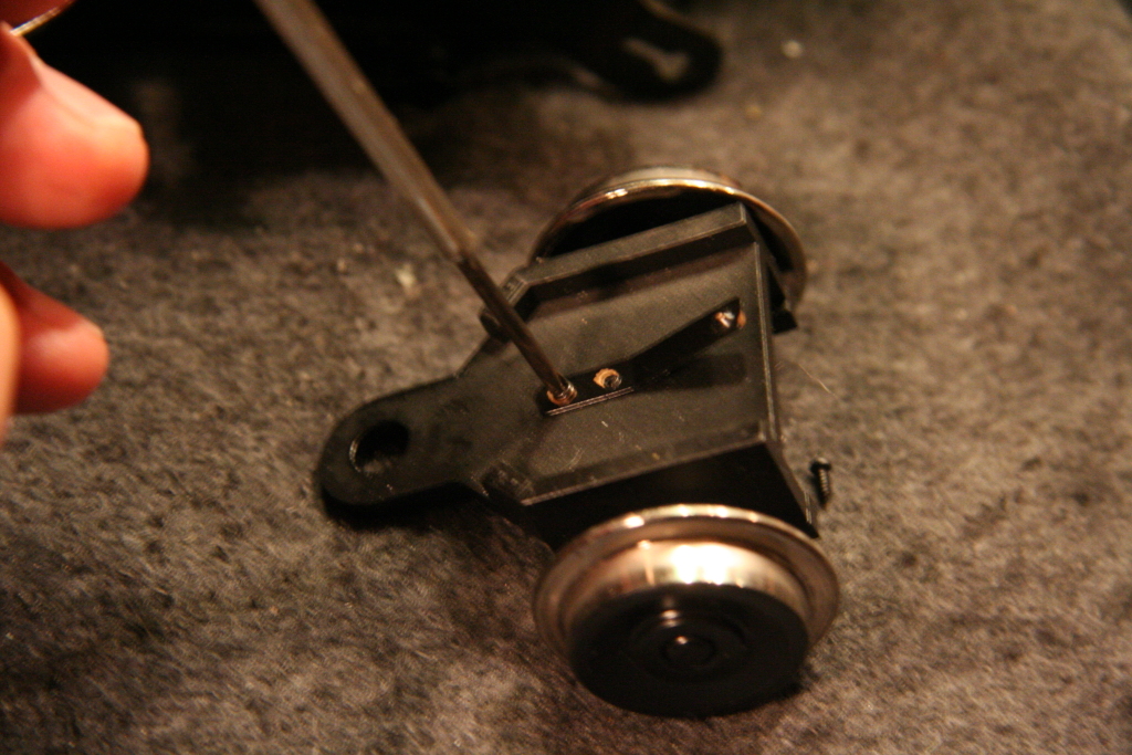
A quick way to increase the downward pressure the metal tab has is to flip the tap around 180 degrees. To remove the lead truck, unscrew the pivot screw at the rear. Once removed, use a small jewelers phillips head screwdriver to remove the small screws holding the metal tab on. Once off rotate the tab around and screw back down. (You may want to bend up the tab some for increased downward pressure.)
|
|
|
||
It is important to note that this alone works fine if the engine is run on 20ft diameter curves. If the curves are tighter, you may have an issue with the tab moving off the flat bottom surface of the motor block above and slide the diagonal side of the surface which may cause issues. For maximum flexibility to run the engine on any layout an additional plate extension needs to be added to the bottom of the frame (not pictured).
_________________________________________________________________________________
11/21/2010
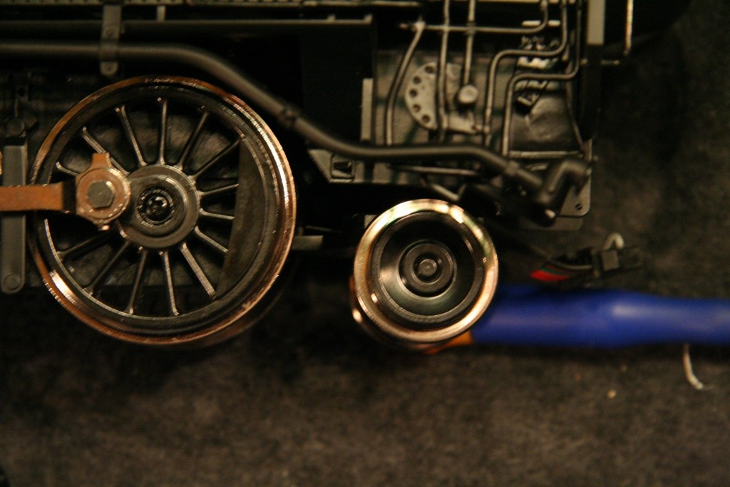
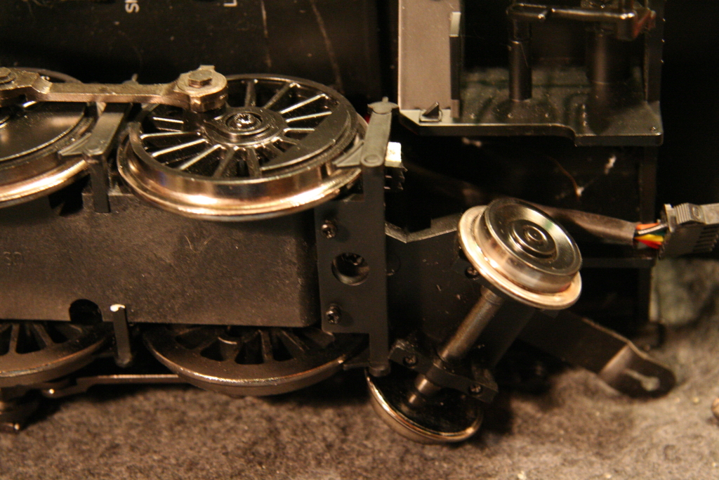
Increase downward pressure on trailing truck
Similar to the modification above on the lead truck, the same can be done for the trailing truck to increase downward pressure.
(NOTE: If your engine and tender drawbar connections are still in their original configuration, you will not want to do this modification as it will increase the issue of the two coming uncoupled. My drawbar connections have been modified in such a way that that makes this modification works ok. See Vanderbuilt tender custom drawbar replacement / improvement for more information.)
To modify, first unscrew and remove the rear brake shoes. Then unscrew the retaining screw holding the trailing truck and engine drawbar assemblies.
|
|
|
|
|
Next, unscrew the metal tab and rotate 180 degrees and reassemble.
|
|
|||
While a new wider custom tab would be ideal, this modification works as is.
_________________________________________________________________________________
11/21/2010
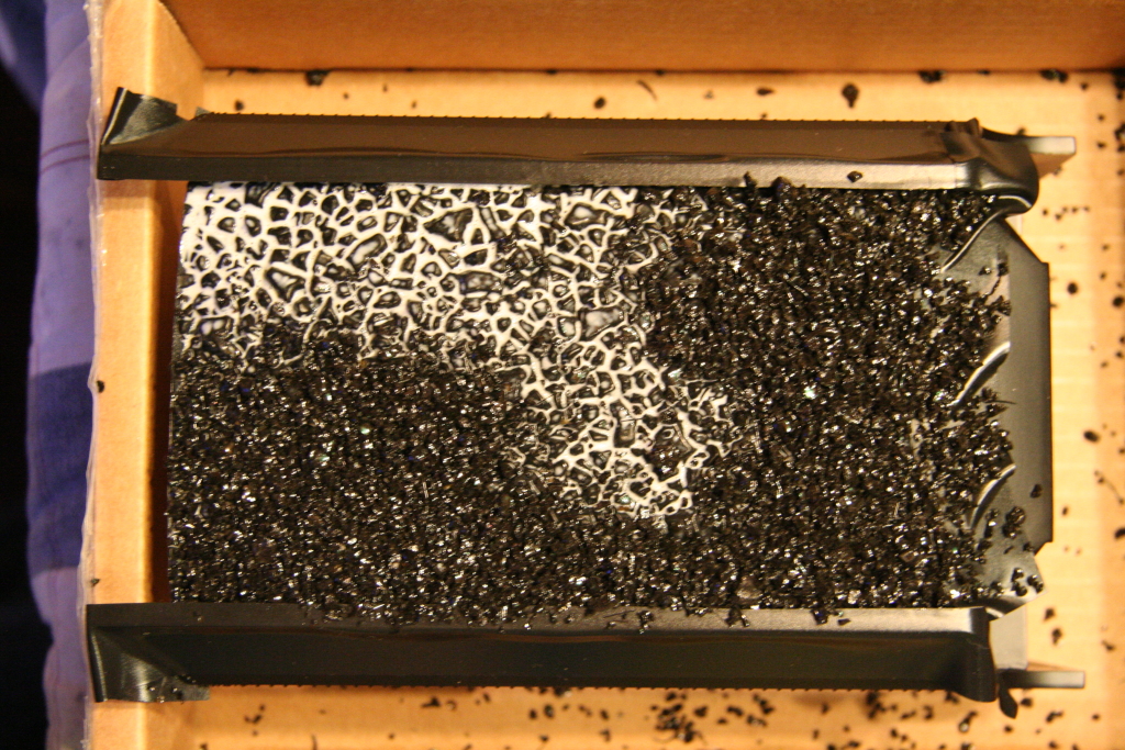
Adding a real coal load to the coal tender
Aristocraft coal tenders do not have any form or type of coal to simulate a coal load.
|
||||
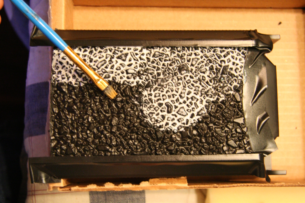
The first step to add coal is to tape off all nearby surfaces that you do not want to get glue on. Next take a brush and apply the desired adhesive (in this case 50% Mod Podge 50% Water with few drops of rubbing alcohol) over all the surfaces you want covered with coal.
|
|
|||
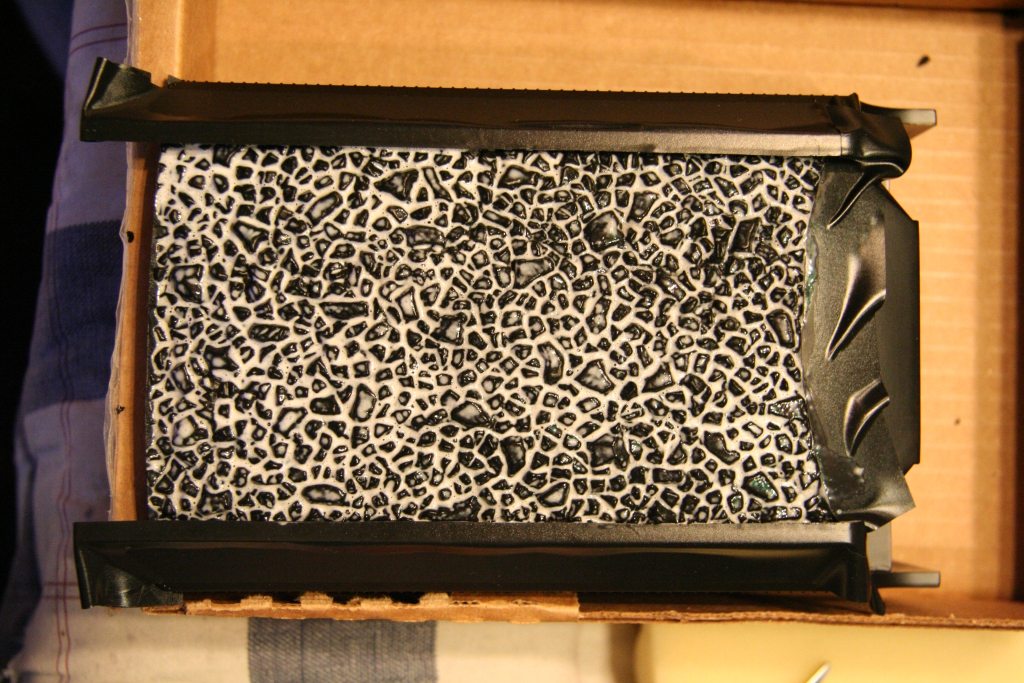
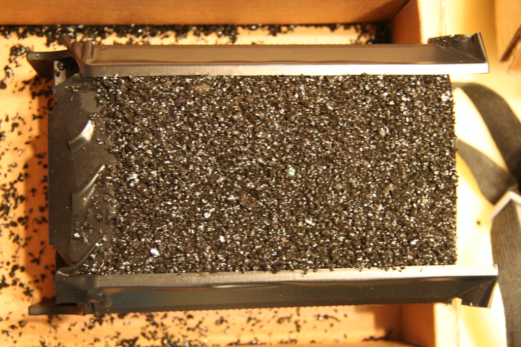
Next, place the tender/cover over a box and sprinkle the coal on and add enough to create the desired form and height.
|
|
|||
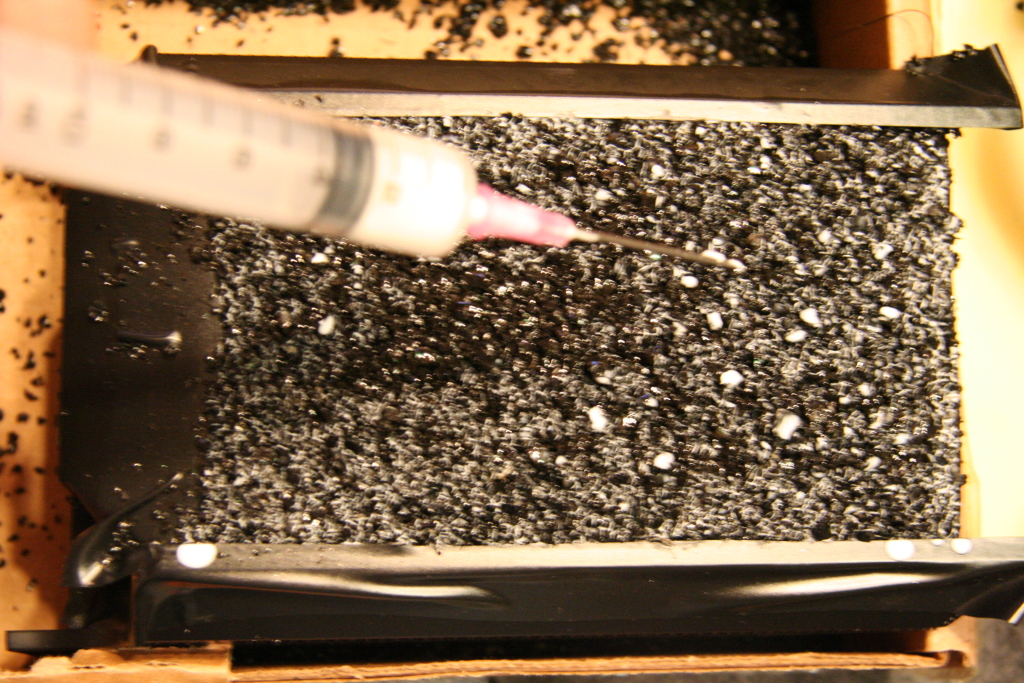
Then using a dropper, drip additional adhesive over the entire top surface of the coal load. Be sure to add enough so it works it's way to the bottom. (You need to try and find a right balance between too little and too much.) Let the glue dry for 12-24 hours and be careful to not tip or shake.
|
|
|||
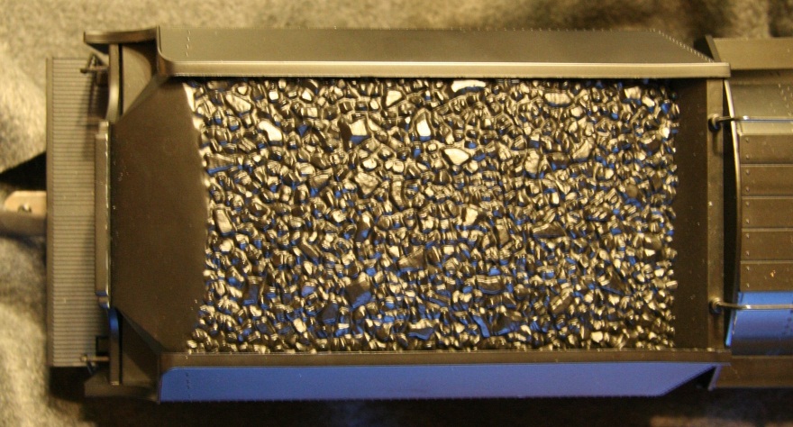
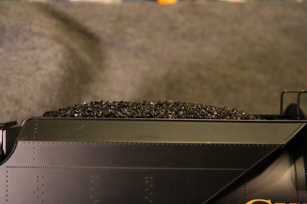
Here is the finished product.
|
|
|
||
__________________________________________________________________________________
12/27/09
Sealing the Aristocraft smoke unit fluid reservoir tank to prevent leaks:
I've found most of the Aristocraft smoke units leak around the inside wall when fluid is added. To keep this from happening, I run a bead of superglue along the outside corner of the inside wall to seal it. Once sealed it won't leak anymore. I usually let it sit overnight to fully dry before reassembling.
|
|
|
||
__________________________________________________________________________________
11/27/10
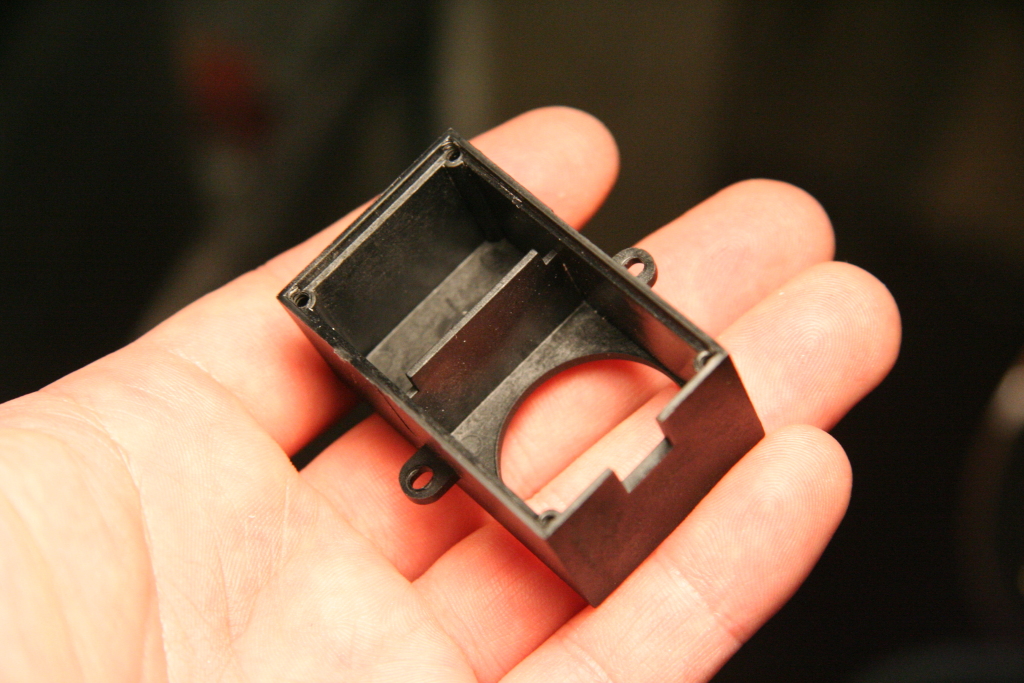
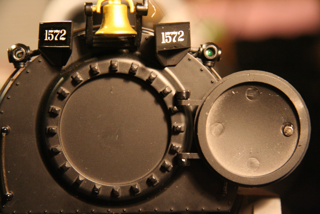
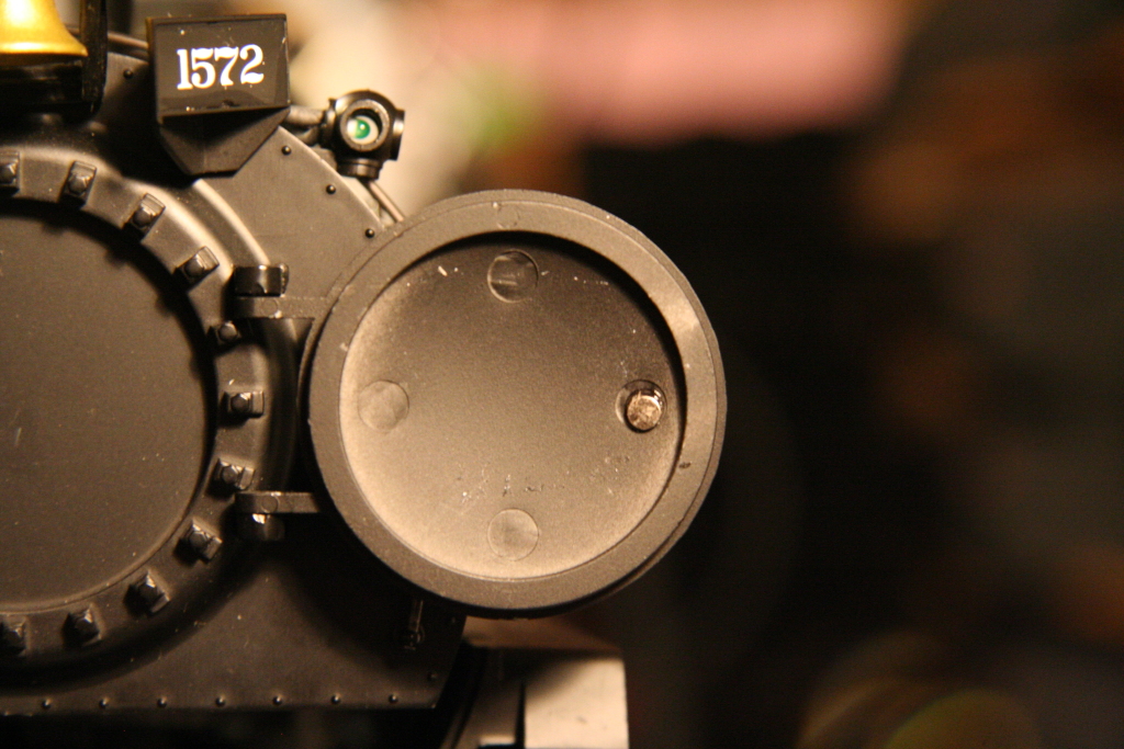
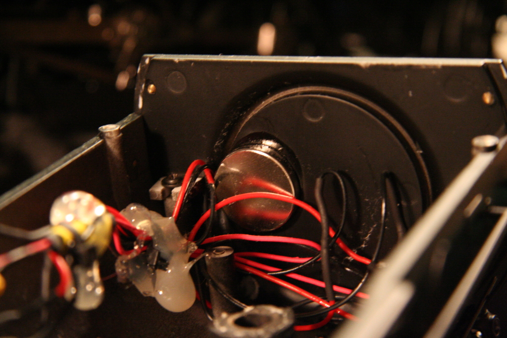
Install magnets to keep the smoke box door closed:
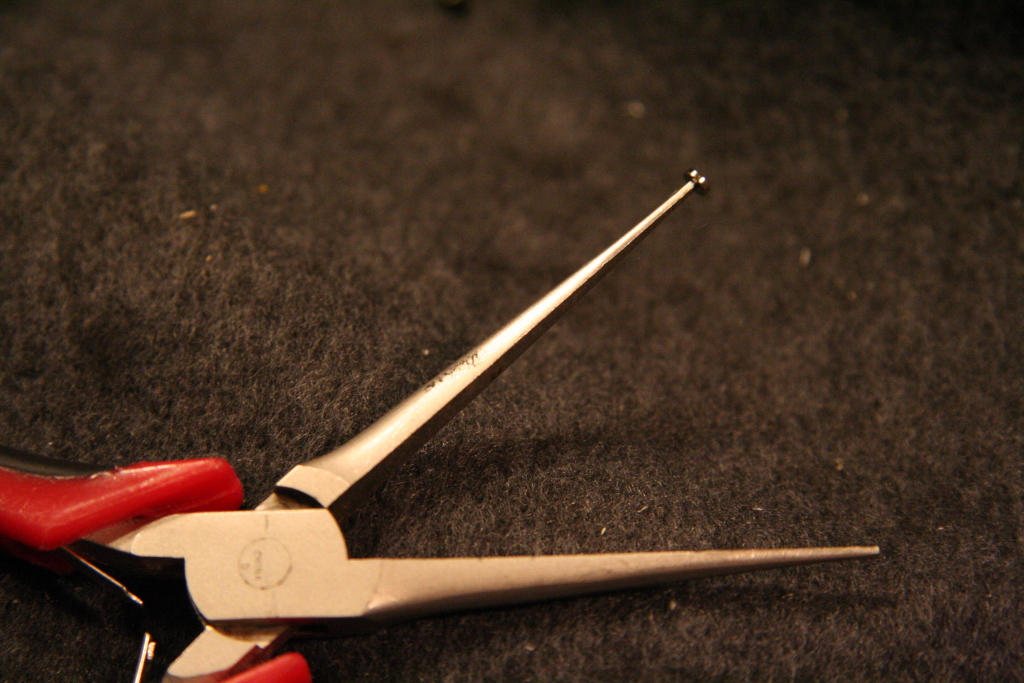
The mallet smoke box doors have a tendency work their way open either due to vibration or wind. In order to keep them closed but still allow them to be opened easily I added installed magnets on both the door and behind the inside of the boiler behind the back smoke box front. To glue the small magnet on, I put it on the end of a pair of pliers and held it in place till the superglue was secure. (If you want a pair of these magnets to install on yours I have a few avail for $6.00 + $2.50 shipping)
|
|
|
|
|
__________________________________________________________________________________
Return to Garden Railroad Modification page.