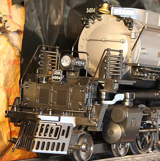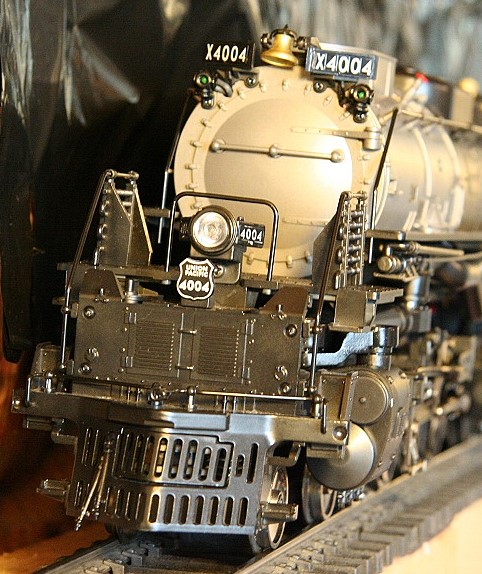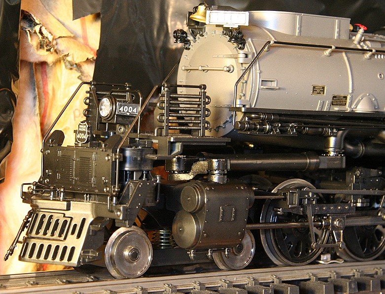
MTH: Big Boy Repair/Modifications page:
(Click here for MTH: Big Boy - Photo & Video Page)
See Sales and Pricing page for availability: Sales and Pricing - MTH One Gauge
Model Info: MTH One Gauge Big Boy w/Protosound 2 - Protosound 3 - DCS - 70-3009-1 - 70-3026-1
MTH Product Pages:
Union Pacific #4004: w/PS2.0 (70-3009-1): http://www.mthtrains.com/70-3009-1 - (2004 model) (June 2004, Delivery=June 2006)
Union Pacific #4014 oil: w/PS3.0 (70-3026-1): http://www.mthtrains.com/70-3026-1 - (2015 model) (Announced 4/25/2015, Delivery=3/25/17)
Union Pacific #4012: w/PS3.0 (70-3027-1): http://www.mthtrains.com/70-3027-1 - (2015 model) (Announced 4/25/2015, Delivery=3/25/17)
Union Pacific #4014 coal: w/PS3.0 (70-3037-1): http://www.mthtrains.com/70-3037-1 - (2018 model) (Announced 5/9/2018, Delivery=7/12/18)
Union Pacific #4006: w/PS3.0 (70-3038-1): http://www.mthtrains.com/70-3038-1 - (2018 model) (Announced 5/9/2018, Delivery=7/12/18)
Union Pacific #4018: w/PS3.0 (70-3039-1): http://www.mthtrains.com/70-3039-1 - (2018 model) (Announced 5/9/2018, Delivery=7/12/18)
Union Pacific #4017: w/PS3.0 (70-3040-1): http://www.mthtrains.com/70-3040-1 - (2018 model) (Announced 5/9/2018, Delivery=7/12/18)
Union Pacific #4023: w/PS3.0 (70-3041-1): http://www.mthtrains.com/70-3041-1 - (2018 model) (Announced 5/9/2018, Delivery=7/12/18)
Union Pacific #4014 oil: w/PS3.0 (70-3048-1): http://www.mthtrains.com/70-3048-1 - (2021 Uncataloged iteml) (Announced 1/15/2021, Delivery=TBD)
Union Pacific #4014 coal: w/PS3.0 (70-3049-1): http://www.mthtrains.com/70-3049-1 - (2021 Uncataloged iteml) (Announced 1/15/2021, Delivery=TBD)
MTH One Gauge Catalogs:
Model Overview: MTH One Gauge Big Boy w/Protosound 2 - Protosound 3 - DCS - 70-3009-1 - 70-3026-1
This is MTH's third One Gauge steam offering and has many upgrades.
________________________________________________________________________________
MTH Big Boy Repair/Modifications: MTH One Gauge Big Boy w/Protosound 2 - Protosound 3 - DCS - 70-3009-1 - 70-3026-1
Modifications/Topics list:
MTH - Big Boy: (Model info)
Front Pilot Spring replacement to get the front engine to sit more evenly - (Applied to 2006 MTH One Gauge Big Boy)
Adding 1 lb 6oz weight to front of boiler to get rear engine to sit more evenly - (Applied to 2006 MTH One Gauge Big Boy)
Note: Changes made for 2015 model help reduce this risk
Slider screw modifications (To stop switch and cross-over shorts)
Slider shoe modifications + shimming the axles (To stop shorts on Aristocraft 19.5 degree cross-overs)
Adding fuses between front and rear engine power pickup wires to protect from short damage
Electrically isolating two pin component from the frame - (Applied to 2006 MTH One Gauge Big Boy)
Sliders getting caught in switch frogs. (Particularly #6 switches)
Driveline binding / not running smooth - (Applied to 2006 MTH One Gauge Big Boy)
Brake shoes facing the wrong way - (Applied to 2006 MTH One Gauge Big Boy)
Drawbar upgrade and modification - (Applied to 2006 MTH One Gauge Big Boy)
Tender Plug Problems (Sound cutting out/intermittent) - (Applied to 2006 MTH One Gauge Big Boy)
Charging the engine's PS2 on-board battery - (Applied to 2006 MTH One Gauge Big Boy)
Sound file update: Corrects S01 softkey short whistle sound - (Applied to 2006 MTH One Gauge Big Boy)
Polarity switch location - (Applied to 2006 MTH One Gauge Big Boy)
________________________________________________________________________________
08/03/2006 MTH One Gauge Big Boy w/Protosound 2 - Protosound 3 - DCS - 70-3009-1 - 70-3026-1
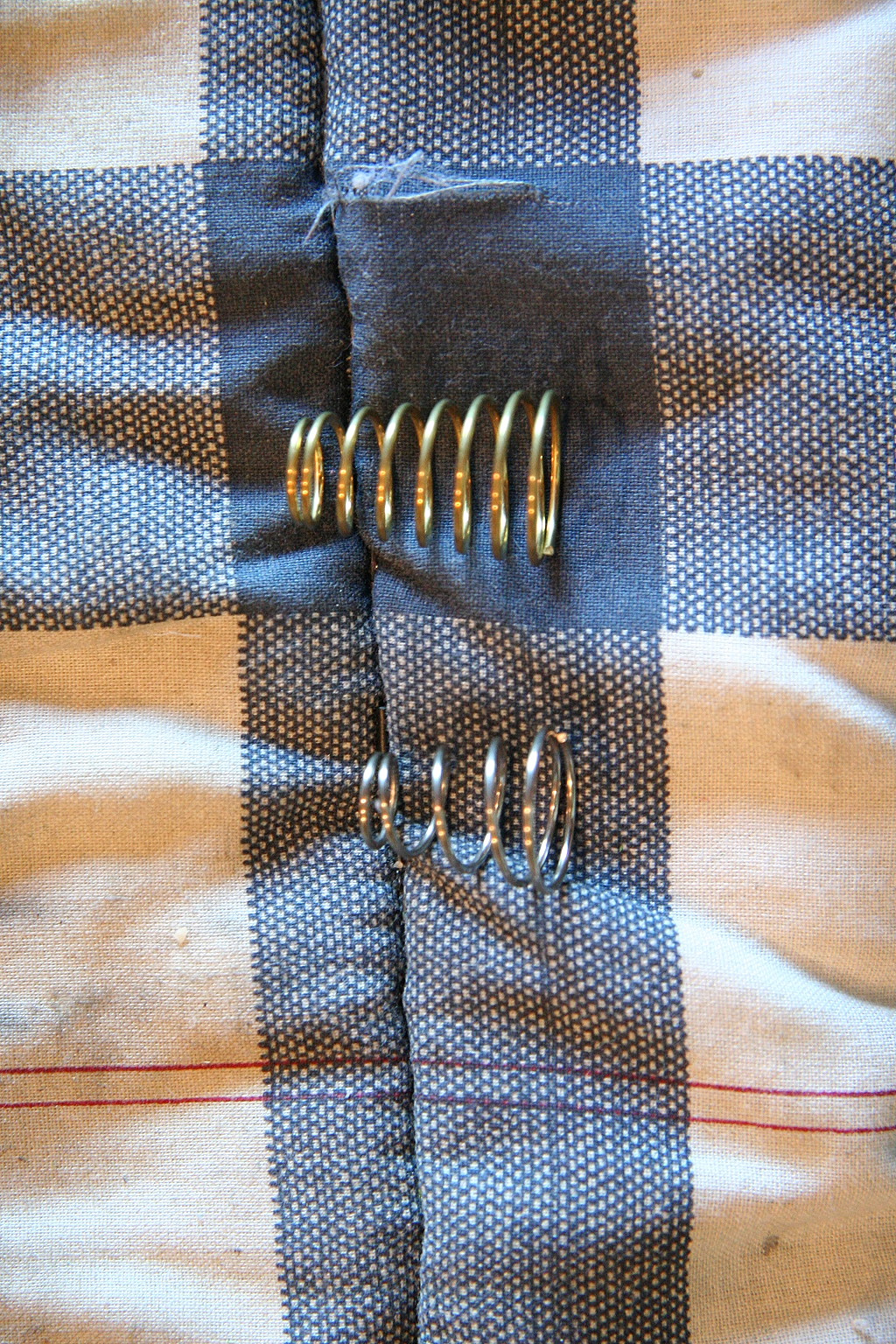
Front pilot spring replacement:
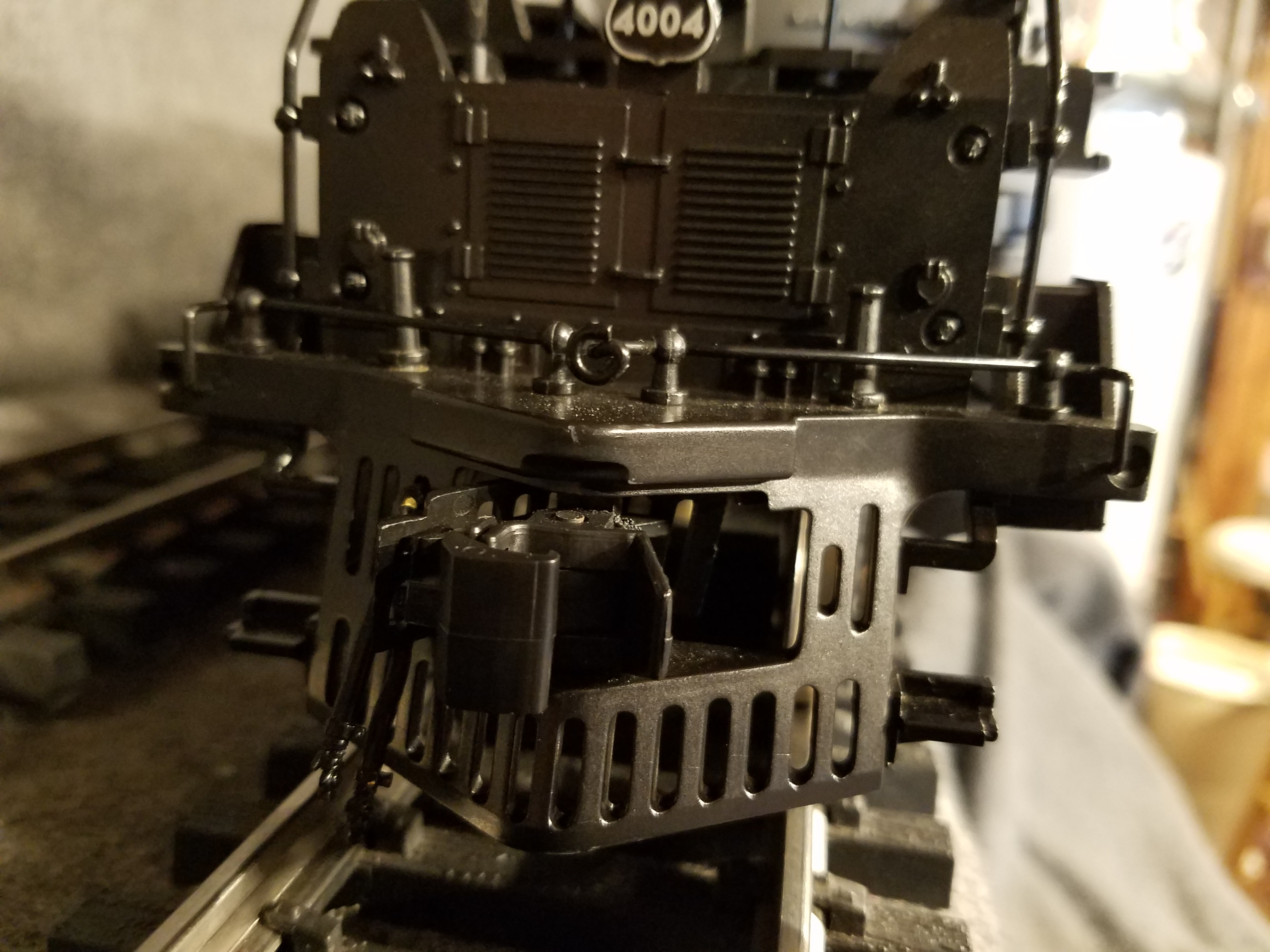
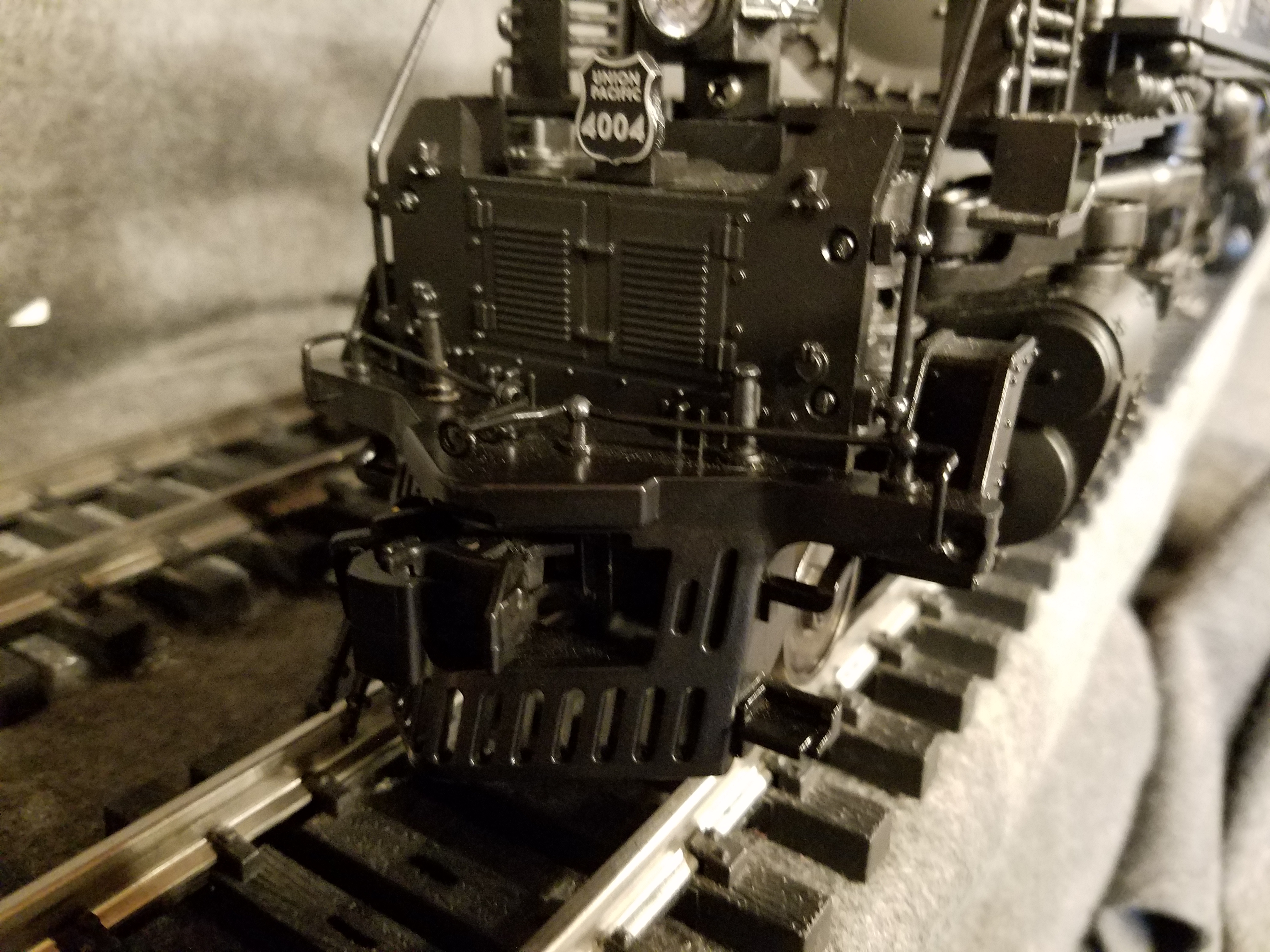
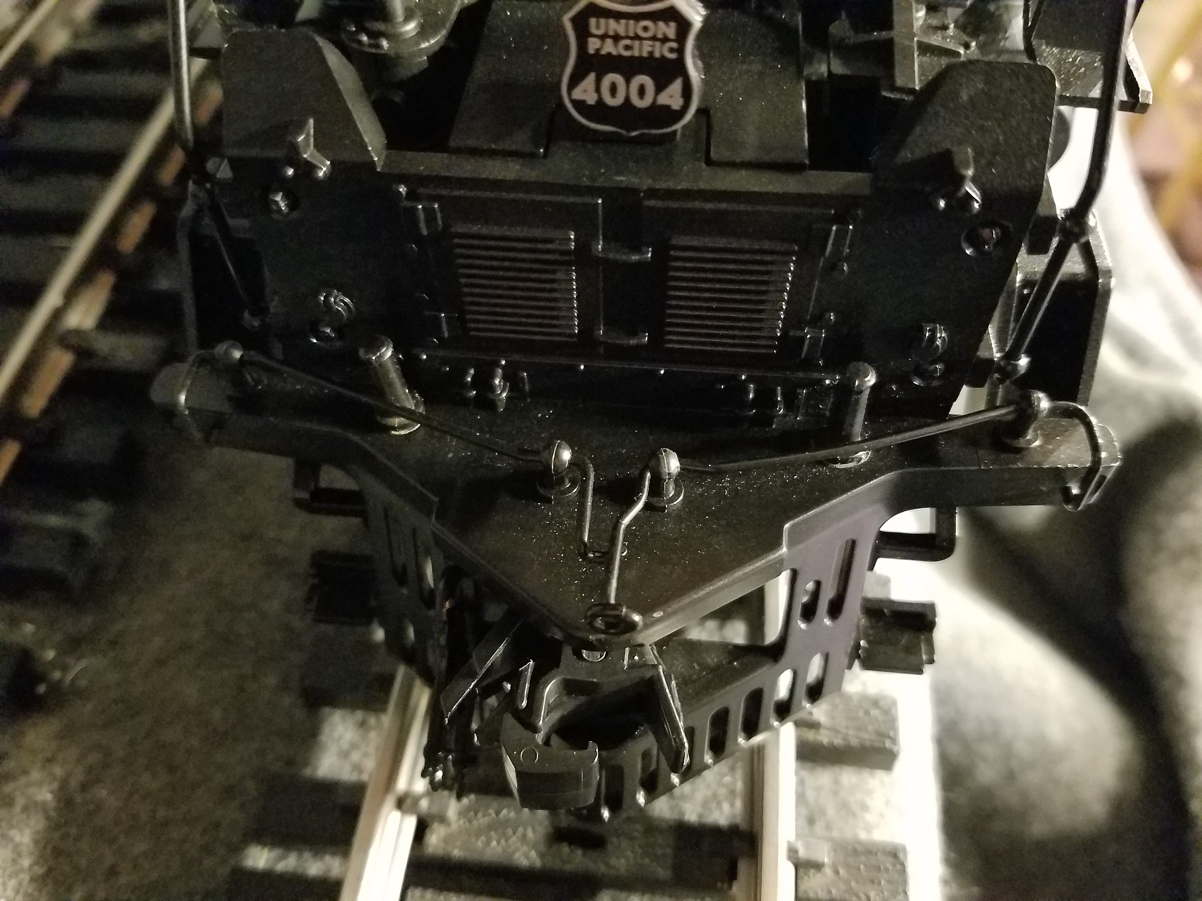
One of the first things I noticed upon first inspecting the new MTH Big Boys was the front and rear engine sets #1 drivers had very little weight and were only just making contact with the track. (Which to be sure is a very minor issue)
On the front engine set, this was because the new spring used on the lead truck was too strong and was pushing to hard up on the front pilot. To resolve, I replaced the original with the brass spring pictured below (purchased from Ace Hardware - #138 - Item#18649). The replacement spring was more like the one used on the original MTH Challenger... it's not as strong but still allows for enough force to keep the truck on the track. In my case I snipped one complete circle of spring off the wide bottom part to reduce the spring strength even further.
Original spring (bottom), new replacement (gold colored on top):
|
||||
Adding weight to the front of the boiler:
To balance out part of the upward pressure on the front of the boiler (and thus removing weight from the #1 driver on the rear engine set) I determined additional weight was necessary in the front of the boiler and added ~1 lb 6oz inside the front of the boiler. (The optimal desired weight will depend on how far towards the front the weight is added and of course the amount of weight doesn't need to be precise.) Weight can be added on the flat bottom part of the boiler behind the smoke unit or on the sides of the boiler in front of and behind where the front motor fits into the boiler.
I've found the best adhesive is to use hot glue.
_________________________________________________________________________________
08/03/2006 MTH One Gauge Big Boy w/Protosound 2 - Protosound 3 - DCS - 70-3009-1 - 70-3026-1
Engine shutting down intermittently / Power pickup problems / Loss of track power pickup from the front engine set:
(Unnoticeable Shorting on Switches & Aristocraft 19.5 Degree cross-overs)
Note: Modifications made to the 2015 model reduce this risk
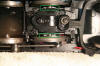
If you have problems with your engine intermittently shutting down (which is a symptom of a poor power pickup or a power pickup problem), you may have a burned out power transfer trace on the rear power transfer board located under the rear set of engines. This can happen if one of the following occurs:
- Slider screw head touches the top of an opposing rail as the engine goes through a switch/crossover if it's sticking down too far. (This is the most common problem - See below: Slider Screw shorts)
- The engine derails in certain way that causes a direct short between the front and rear engine power pickups. (This is less common but can happen during accidental derailments)
- Running the engine through an Aristocraft 19.5 degree crossovers (and possibly other brands of crossovers)
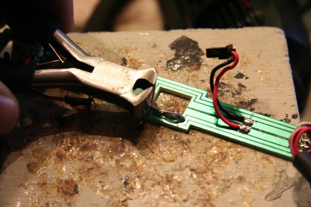
To inspect to see if your board has a burned out trace, you need to remove the bottom plate located under the rear engine set (wheels) by removing the screws holding it in place. Once loose, the board is connected at the front and back by two connector plugs which you will need to pull on to unplug. Once out, inspect all the power traces on the entire board (paths that are connected to the red and black wires). Look for any areas of abnormality where the path is black in color. The photo below shows the most common location for the power trace to burn out. (I have seen other locations further down the board with power trace breaks so check carefully.)
|
|
|||
Repairing a burned trace:
The best solution to fix the trace damage is to solder a jumper wire to bridge the broken power trace. To do this, scrap off the circuit board coating on either side of trace and expose the copper. Then heat and add solder to those exposed points. Next, take a copper wire and add solder a length of it. Then solder the wire to the area on the board you just prepped and soldered. Cut the excess length off with wire cutters. Ensure the exposed wire does not come in contact with the frame above when reinstalling. You may want to attempt to insulate the exposed wire with thin layer of hot glue or electrical tape.
|
|
|
|
|||
Prevent burned traces from happening again:
If you just have switches on your layout (no 19.5 degree cross-overs) then do the following:
- Add fuse between front and rear engine sets as additional protection (not required but recommended)
If you have 19.5 degree cross-overs then do one or both of the following steps (in addition to the above two):
- Modify the 19.5 degree cross-over
and/or
- Add shims to driver axles to reduce side to side motion of frame on axles
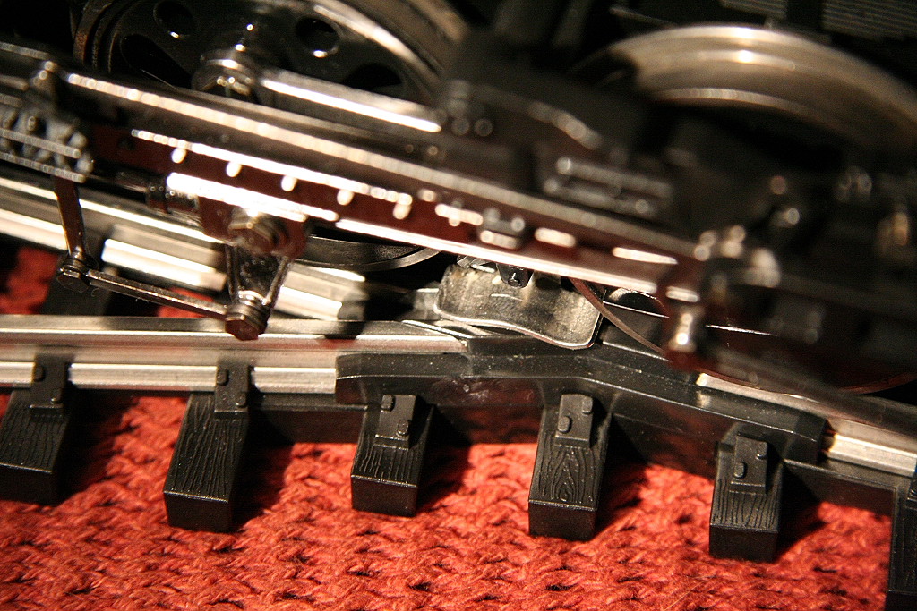
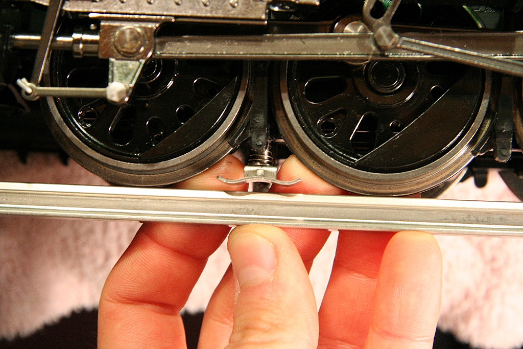
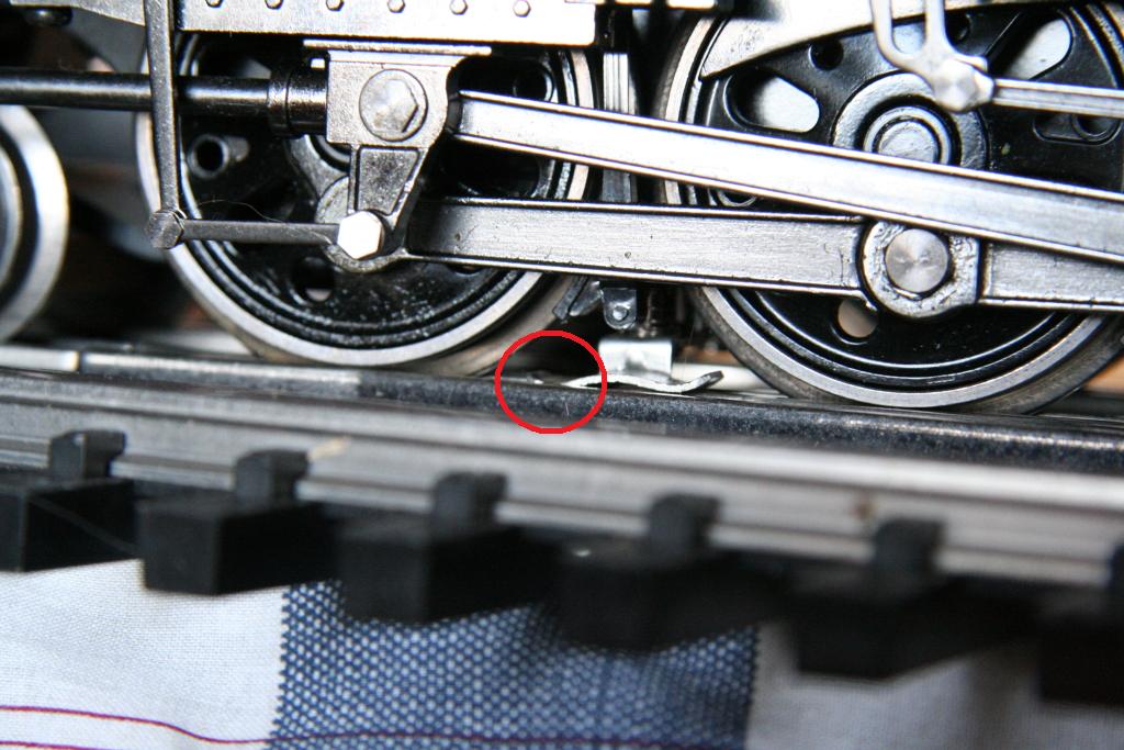
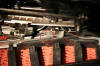
Slider Screws causing shorts on Switches & Cross-overs:
There is also a risk of the slider screw sticking down too far and making contact with the top of the crossover & switch rails that pass under the engine and is the most frequent cause for damaged traces.
To prevent this, you will want to first ensure each screw is fully screwed in place. Next, the spacing between the switch/crossover rail heads and each slider screw should be checked. Even when fully screwed in place, you may find variations and some able to make contact or with very little safety margin between the screw head and the top of the rail.
On all of my engines I filed the screw head down almost flat, leaving just enough of the original screw slot to allow use with a screw driver. Doing this alone will add quite a bit to the safety margin and may be all you need to do. You may also find that the other end of the slider screw will need to be filed down to allow it to screw further into engine.
Slider shoes causing shorts on Cross-overs:
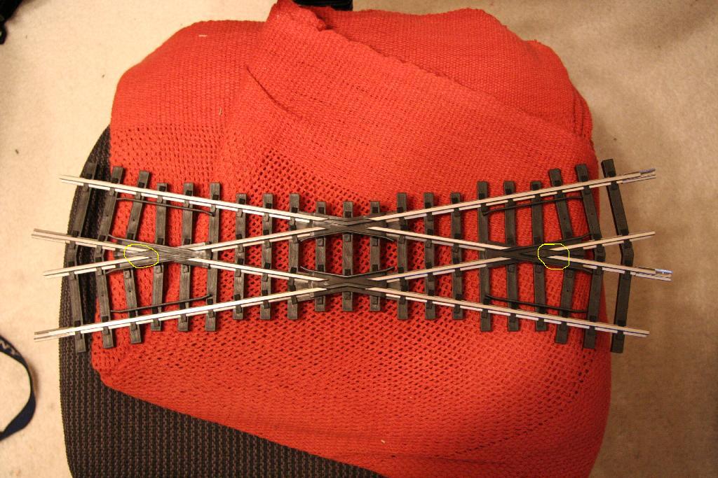
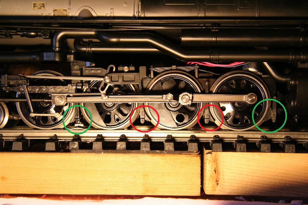
Bench testing revealed an issue with shorting 19.5 degree crossovers and the cause to be two-fold (with a possible third issue): (please note that the issue of crossover shorts is limited to the 19.5 deg crossover (by Aristocraft), 30 deg and 90 deg versions should not have this issue.
The side to side play of the frame on the axles is so great, it allows the sliders to swing out over the opposing rails in the cross-over which leads to a short.
The sliders themselves are too wide and stick out too far on the side
Possible issue with power slider screws stick down too far (see Slider Screw Shorts below)
Here are some photos of the overlap I'm talking about. In the photo of the crossover, the most critical short points are circled in yellow. It should be noted however, the inside of the slider can also short on the inside cross-over rails.
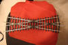
With frame swung to the left.
With frame swung to the right. (there is a risk of shorting on the inside rails)
TO PREVENT SLIDERS FROM SHORTING ON THE 19.5 CROSS-OVERS:
You can either:
Option 1: Modify the engine as seen immediately below by modifying the sliders and adding nylon axle shims (and possibly adding fuses)
and/or
Option 2: Modify the cross-over. See 19.5 Degree crossover modification to eliminate the risk of electrical shorts from engine power pickup sliders
Option 1: (To fix 19.5 degree cross-over shorts)
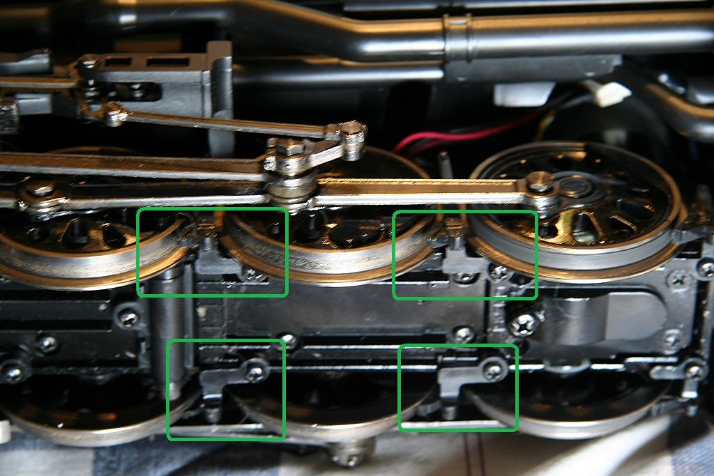
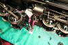
MODIFYING THE ENGINE: (Shimming the Axles & Reducing Slider Width)
Shimming the Axles: (Step 1 of 2)
First, I added nylon washers purchased at Home Depot on both sides of the first and fourth axles on both the front and rear engine sets. (total of 8 washers.) This significantly reduced the side to side play of each engine set and reduced how far over the slider would reach to the opposing rails. To fit on the axle, I cut a pie shaped section out so it could be pressed on from behind and snap on.


Here are the washers installed.

(The engines have been tested on tight 8ft diameter curves so shimming the axles with nylon washers should not limiting your ability to run on tight curves.)
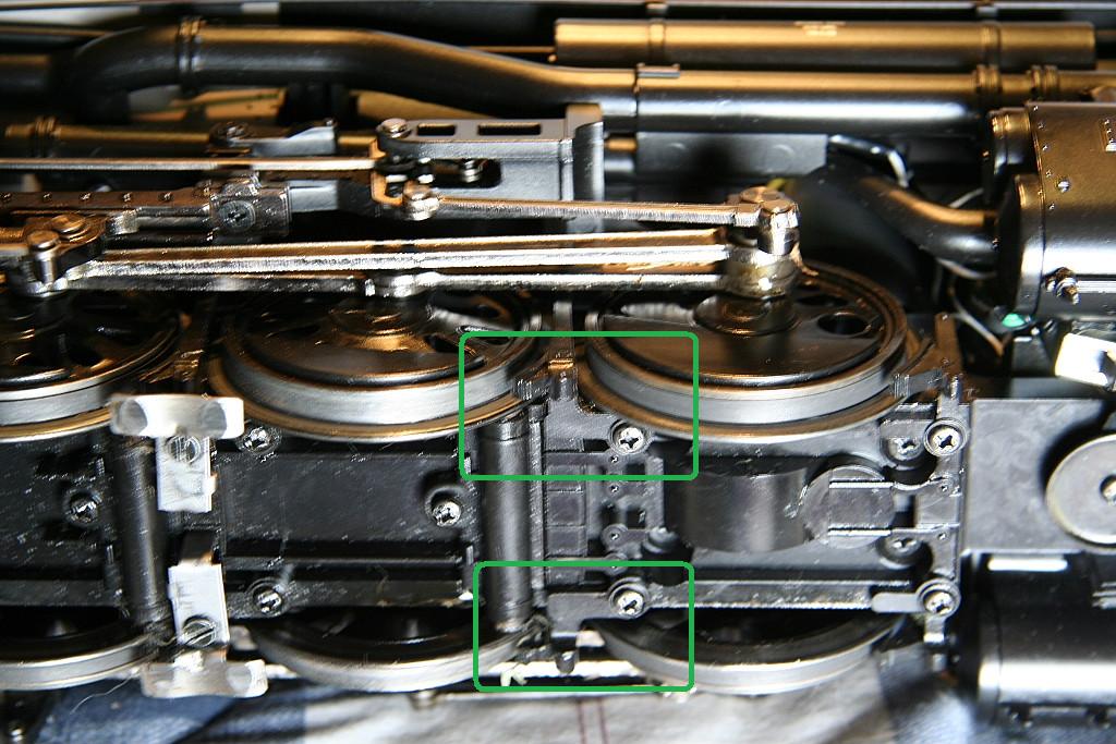
Reducing slider width: (Step 2 of 2)
The other part I found necessary, was to grind down the sides of the sliders to 7mm. In my cause I used the grinding wheel and wire wheel on my bench grinder.
(Note: that reducing the width will make the outer edge slightly more susceptible to dipping in the frogs of #6 switches. This may happen if the slider is too far out of alignment/level . See Sliders getting caught in switch frogs for more info)

Option 2: (To fix 19.5 degree cross-over shorts)
MODIFYING THE 19.5 CROSS-OVER
_________________________________________________________________________________
07/15/2007 MTH One Gauge Big Boy w/Protosound 2 - Protosound 3 - DCS - 70-3009-1 - 70-3026-1
Adding fuses between front and rear engine power pickup
wires
to protect from short damage:
OPTION 1:
As a preventive measure to protect the rear power distribution board traces from burnout, I added two fuses one in each power pickup wire between the front and rear engine sets.
I purchased a pair of posi-lock fuse holders (http://www.posi-lock.com/newproducts.html) and added a 3amp fuse. This install was easy and simple to accomplish and only required that you remove the front engine set.

In testing, I found the power traces most susceptible to damage would handle ~4amps max before visible damage occurred and that a 3amp fuse provided the right level of protection.
OPTION 2:
Another option is to sever the power pickup wire connections before going into the front of the rear engine set and re-route them to the back of the engine where the wires connect to the rear connection of the rear engine set. Doing this would allow the use of a much larger fuse (5amp+) as the power traces from the rear end of the board are more robust and can handle more current safely. I would still locate the fuse holders in the same place for easy access. Being able to use a higher amp fuse may reduce the likelihood of the fuse actually blowing.
_________________________________________________________________________________
08/03/2006 MTH One Gauge Big Boy w/Protosound 2 - Protosound 3 - DCS - 70-3009-1 - 70-3026-1
Wheel power pickups modification: (Short potential)
You may want to inspect the wheel power pickups to ensure the bare wires from the brushes don't make contact with the metal frame. This could possibly lead to a short with the two pin component that is bolted to the inside top of the rear portion of the frame. (or through other accidentally pinched wires.) Because of the coating on the frame, the chance of an actual short occurring is slim, but it's a possibility.
Below is a picture of one of these wires pinched between the wheel pickup assembly and the frame.
|
||||
To eliminate this as a possible problem, I removed each wheel power pickup and applied a layer of electrical tape on top of the wires to ensure they stayed electrically insulated from the frame above. (Do note that I have not had any shorts as a result of this condition, this was just as a precaution.)
|
|
|||
_________________________________________________________________________________
08/03/2006 MTH One Gauge Big Boy w/Protosound 2 - Protosound 3 - DCS - 70-3009-1 - 70-3026-1
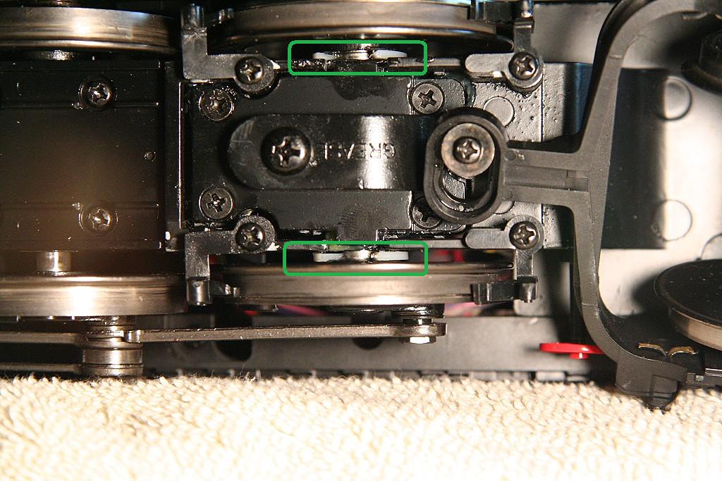
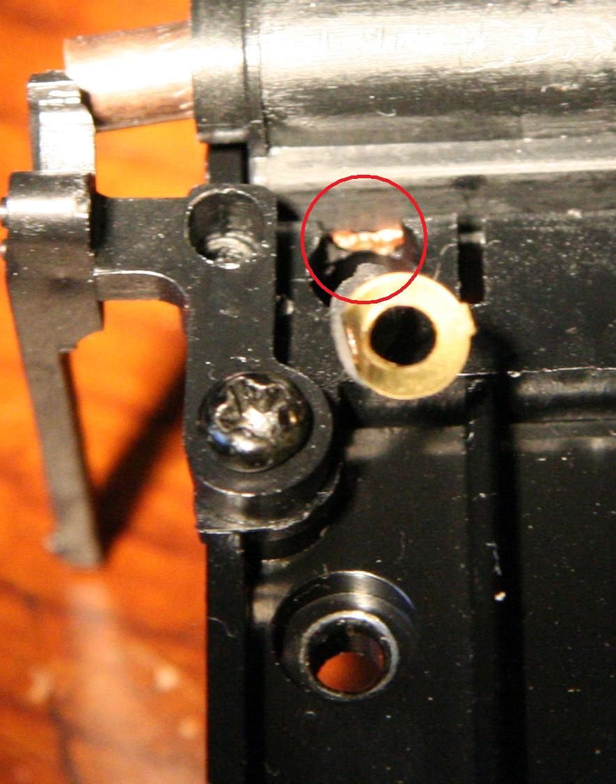
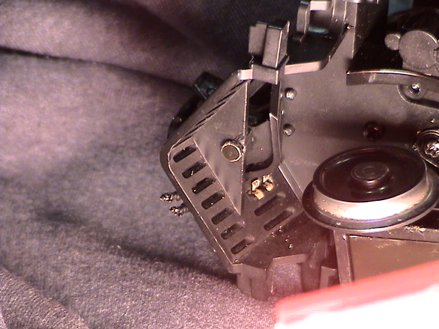
Firebox light frame modification: (Short potential)
In one of the early test runs of the engine on my test track I observed a bright flash at the rear of the conductor's side of the firebox.
A short time later I noticed the conductor side firebox light was coming on with the track power before I performed the DCS startup. (This indicated that light circuit was no longer able to be controlled by the DCS electronics.) After some additional inspection I discovered the cause...
The frame used to support and supply power to the side firebox lights can make contact with the metal frame of the engine creating a short between the firebox light circuit and the uninsulated two pin component. (The distance between the bottom of the firebox bracket from the bottom of the firebox on the boiler shell is 13mm. The height of the frame is 14mm and the frame bottom sits flush with the bottom of the firebox on the boiler shell... which means contact is possible with the 1mm overlap)
To ensure a firebox light bracket to frame short can never happen again, I applied a layer of electrical tape to the frame where it slides next to the firebox light frames. (Pictured below)
Also pictured is the the two pin component (with the red and yellow wires) which I chose to electrically isolate from the frame. (See Electrically Isolating the two pin component from the frame section below).
|
|
|
|
|
|
|
Here is a video of a damaged firebox light circuit, notice one of the two rear white firebox lights is already blown from over-voltage of seeing direct track power.
 - Video - 0:56 mins - Firebox light circuit issue
In my case, this engine's main electronics board needed replacement in order to correct the damaged lighting circuit.
Keep in mind the key issue here is the uninsulated two pin component. If you insulate the two pin component, you eliminate the possibility of those two circuits shorting.. however I still feel the application of electrical tape to the frame is still a good idea to ensure an accidental short can never happen again.
__________________________________________________________________________________
09/03/2006 MTH One Gauge Big Boy w/Protosound 2 - Protosound 3 - DCS - 70-3009-1 - 70-3026-1
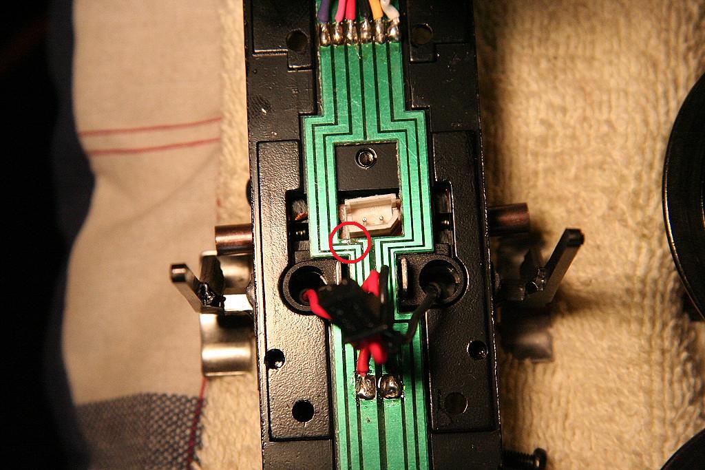
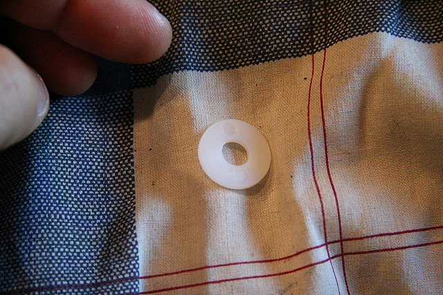
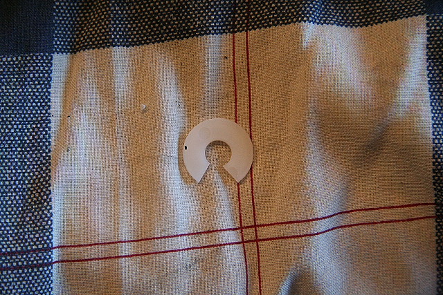
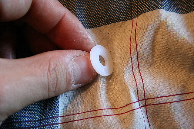
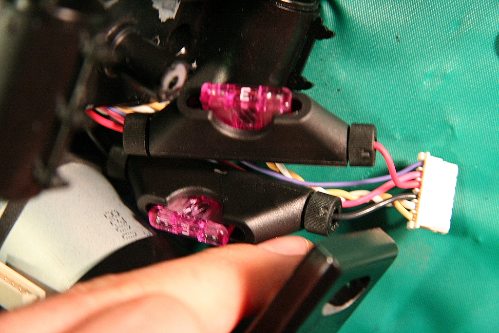
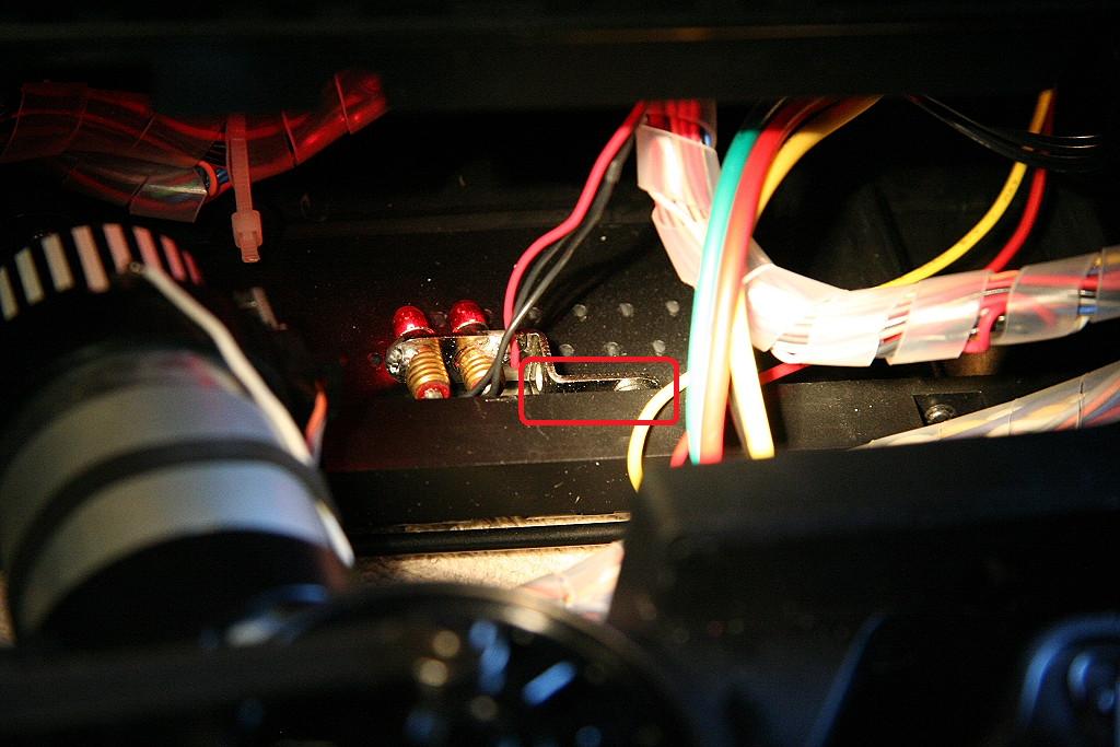
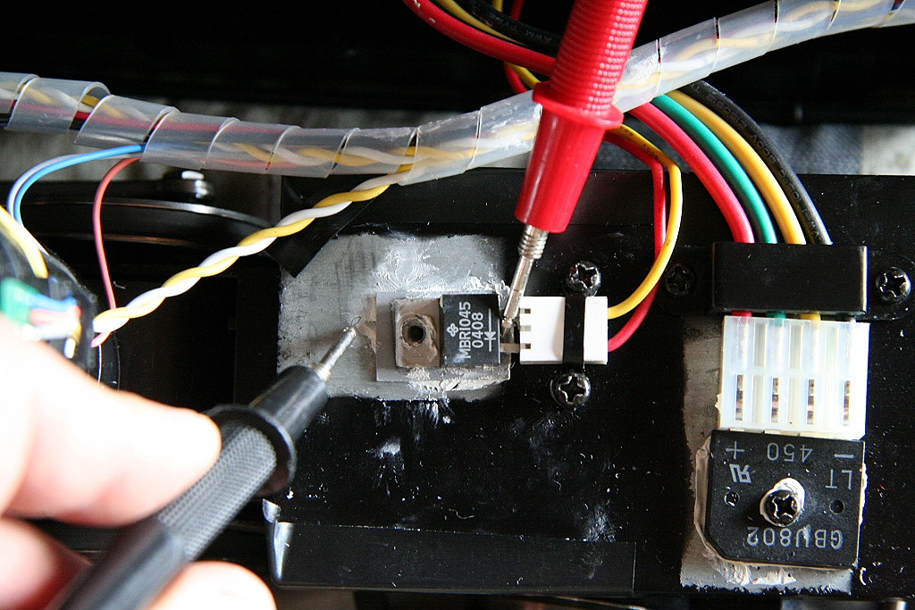
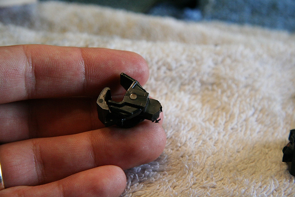
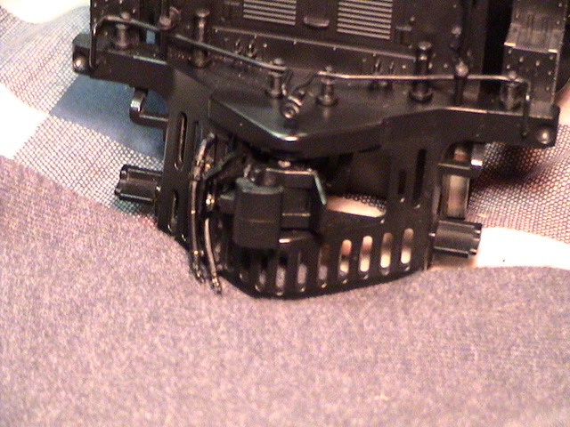
Electrically Isolating the two pin component from the frame - (Applied to 2006 MTH One Gauge Big Boy)
The two pin component that is mounted to the frame didn't have electrical insulators provided to keep it from passing power to the frame.
For illustration: the two pin component is smaller component with the red and yellow wires going to it.
|
||||||
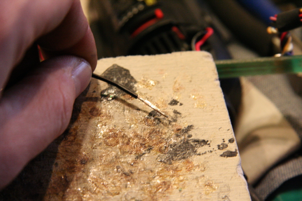
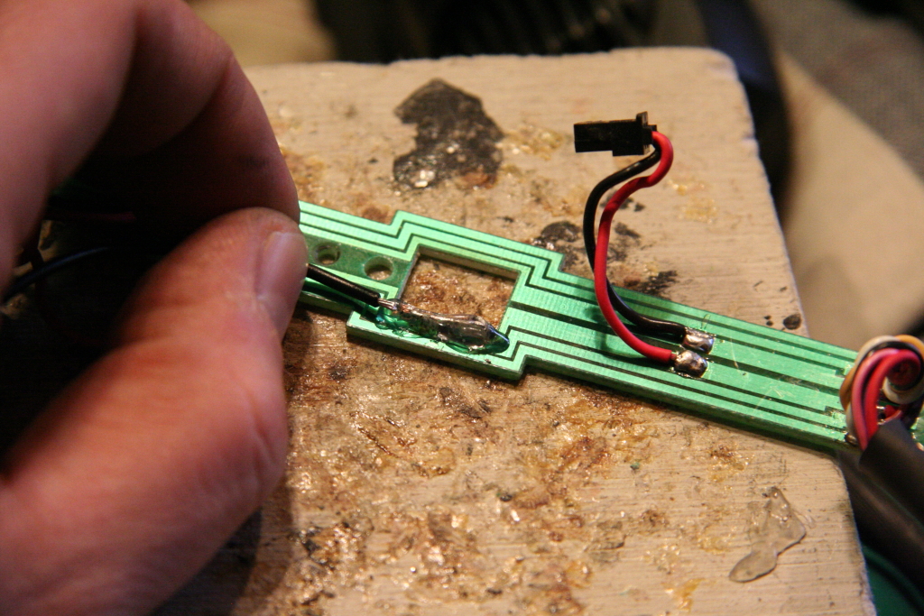
I recommend this be isolated by either adding an insulator (Example: NTE422 (TO220 style) insulator kit) or by removing it off the frame and heat shrinking it and the connector together. My testing has shown the component doesn't generate enough heat to require being heat-sinked to the frame.
|
|
|
|
|
||
The isolator kits can be ordered from Allied Electronics (Allied part # 935-9422). Each pack has two insulators and washers.
_________________________________________________________________________________
09/22/06 (Updated 4/3/17)H One Gauge Big Boy w/Protosound 2 - Protosound 3 - DCS - 70-3009-1 - 70-3026-1
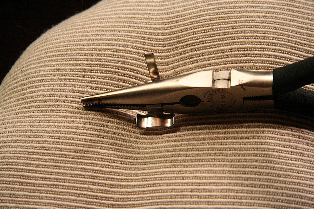
MTH Big Boy - No Flags:
I preferred the look of the engine without the green flags so I removed them.
To remove, cut the tab under the pilot with cutting pliers and push from under the engine with the tip of a Phillips screw driver and carefully work it out.
|
|
|
||
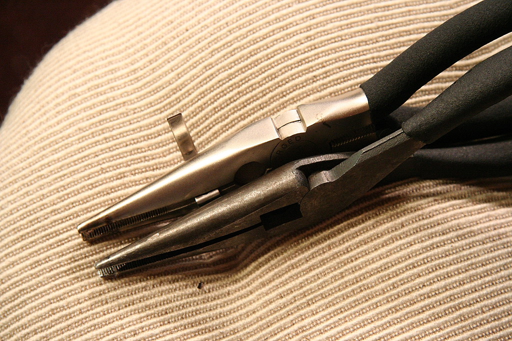
I then cut the flag off the top of the post, sanded and painted to retain the post without the flag:
|
|
|
||
___________________________________________________________________________________
03/04/2009 MTH One Gauge Big Boy w/Protosound 2 - Protosound 3 - DCS - 70-3009-1 - 70-3026-1
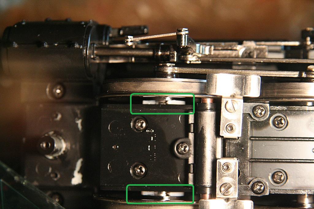
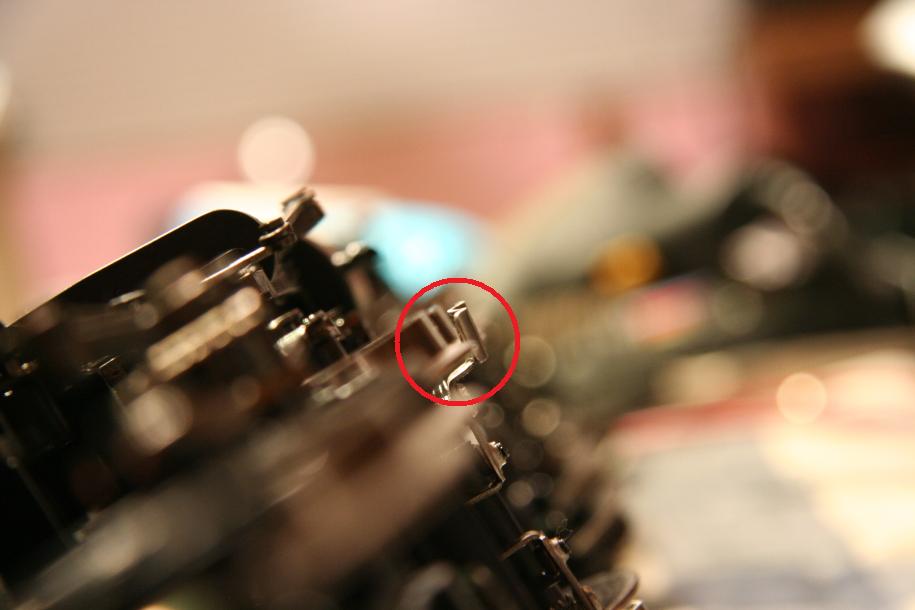
Power Pickup Sliders getting caught in switch frogs (Particularly #6 switches)
For those having problems with their engine having a slider that dips in the frog which causes the engine get hung up or jerk, you will need to modify the slider just a bit.
In some cases, the slider screw hole may not be drilled perfectly straight up and down. This results in the slider being tilted a bit front to back. With the one end of the slider tilted down, that end will have a tendency to drop in the frog as it passes over and get hung up.
The solution I came up with for this was to take and bend the slider pad to compensate and ensure the slider sits level on the track.
I first check to see if the slider is level front to back. (The one in the photo here is already level)
|
||||
Based on which end is dipped down, I know which way to bend the slider head to compensate.
One way to fix is to take the slider off the engine and then use two pairs of pliers to bend the slider shoe pad so it is oriented correctly against the rail. After you bend, reinstall it and check. You may have to repeat these steps a few times to get it just right. To speed this process you may be able to bend the slider with it on the engine by hand.
|
|
|||
The other thing to check for is to make sure the outside edge of the slider is level as well. If the outside end is dipped too far down it can increase the chances of it getting caught as well. To tell if it's level, put the engine on it's side and look down the bottom of the drivers and see how the slider looks in comparison. The slider inner to outer level should match.
|
|
|||
If you still have a slider getting caught in a #6 switch frog, it's probably with the engine entering the main from the siding. (see photos below) If this occurs, you will need to take (likely with a pair of pliers) and bend the end of the slider that's dipping down in frog out just a tad. So in this case below, the left side of the photo is the front of the engine, you need to make the front end of the slider bend out further to the left some. (Assuming the slider is already flat and level from the checks above). Don't bend it too much and remember you are bending it out on the horizontal axis, you want to keep it flat and level. Also, make sure the slider screw is fairly secure in the hole you may need to tighten it down some.
(Note: you may read where some have gone with the method of bending the outside edge of the slider way up to prevent it from getting caught. This is not necessary if you go through these steps noted above. If it's getting caught it's just out of adjustment by likely just a little bit.)
|
|
|||
Once you have your sliders set right they will work reliably from then on, it's just a matter of getting any trouble sliders properly set which really doesn't take too much time.
___________________________________________________________________________________
07/06/2008 MTH One Gauge Big Boy w/Protosound 2 - Protosound 3 - DCS - 70-3009-1 - 70-3026-1
Drive line binding - not running smooth: - (Applied to 2006 MTH One Gauge Big Boy)
Have found this on some engines with varying degrees and is not easy to correct. I believe the main cause is due to side rod holes drilled off-center causing binding. (I originally believed this was due to driver quartering issues) The good way to tell that your engine has this problem is that it will not run smooth at very slow speeds (1-2 smph) and will run worse in one direction than the other.
Here is an example of my MTH Big Boy (#3) with serious drive line binding due to driver quartering issues: (It should be noted that while some engines do have some mild hesitation/binding, this was so far a one of a kind example)
www.rayman4449.com/Big_Boy_3.wmv - 9mb (please excuse the thumping noise, it was a problem with the tape)
The best first solution would be to determine which rods may be out of spec and try to replace them. They dont have to be out of spec by much to cause a problem so it isn't easy to see just by casual observation. You could attempt to oval out the side rods with a drill but must use caution as it can cause binding in opposite direction due to increased slack.
___________________________________________________________________________________
07/06/2008 MTH One Gauge Big Boy w/Protosound 2 - Protosound 3 - DCS - 70-3009-1 - 70-3026-1
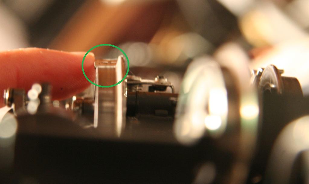
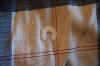
Boiler cracks from the marker light screw holes:
Something to watch for is cracks from the marker light holes.
|
|
|||
I believe there are two factors:
- Marker light screw hole being drilled too small causing the screw to split the plastic
- Pressure being applied to the marker light if tipped on an angle on it's side.
My solution to ensure this doesn't happen on any other engines has been to check the tightness of the screw by trying to back them out. If they were really snug I used a Dremel and drill bit and widened out the hole so it wasn't so tight. Next, use caution when working on the engine and don't put them under too much pressure.
___________________________________________________________________________________
07/26/2008 MTH One Gauge Big Boy w/Protosound 2 - Protosound 3 - DCS - 70-3009-1 - 70-3026-1
Break shoes facing the wrong direction: - (Applied to 2006 MTH One Gauge Big Boy)
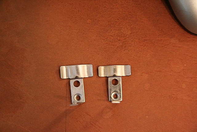
I noticed early on that the brake shoes between the 2nd and 3rd & 3rd and 4th sets of drivers on both engine sets (on both sides) were facing the wrong direction. After some comparisons, I found the factory installed brake shoes that were for a different MTH engine. What is needed are 4 of each of these from their One Gauge Challenger:
Brake Shoe non-slider (right side) - (Need a qty of 4 of this brake shoe)
Brake Shoe non-slider (left side) - (Need a qty of 4 of this brake shoe)
Please contact
me if you need to order these for your engines at:

Photo of the backwards GS-4 shoes:
|
||||
Picture of the correct Challenger versions installed on the Big Boy:
|
||||
Photos of the needed brake shoe needed off the Challenger. (non-slider):
|
|
|||
________________________________________________________________________________
05/17/05 MTH One Gauge Big Boy w/Protosound 2 - Protosound 3 - DCS - 70-3009-1 - 70-3026-1
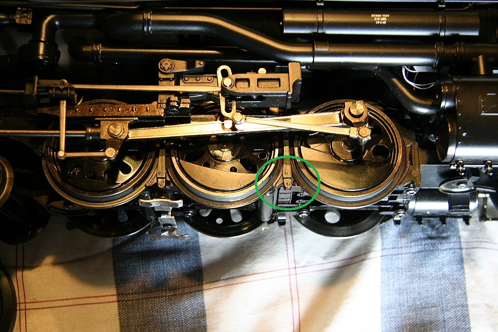
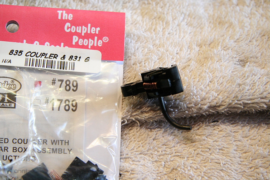
MTH Challenger/Big Boy - G scale Kadee #789 coupler added to the Front:
The Challenger & Big Boy both come with a non-functioning #1 scale size coupler on the front. Not an issue unless you plan to do some sort of lash-up behind another engine or consist.
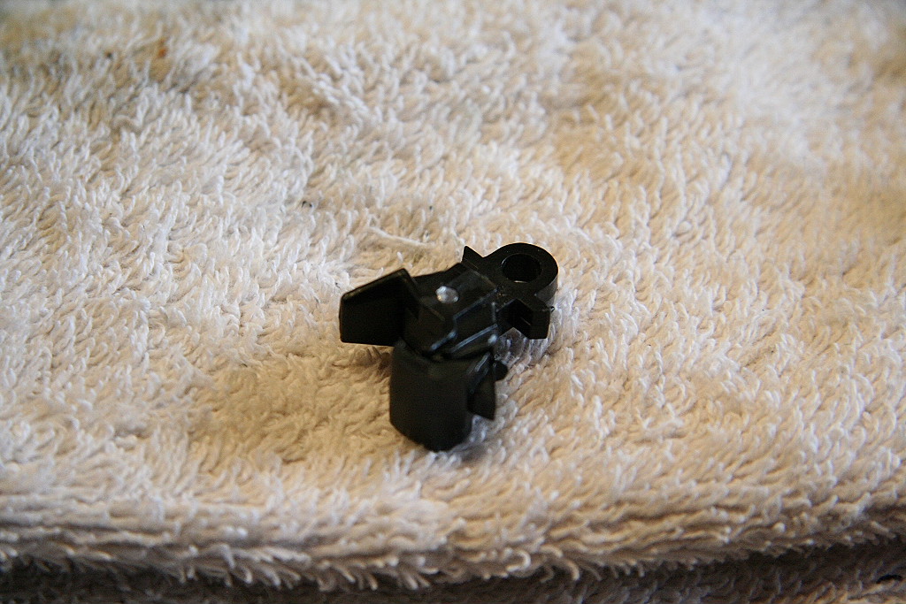
After a bit of modifying I was able to install a Kadee #789 on the front and eliminate the fake one.
Modifications:
|
|
|
|
|
Installed:
|
|
|
|
|
|
|
|
|
|
|
|
||
To accomplish this, you need to pull the pin holding the coupler assembly in place. (from the bottom) It is very difficult to remove and had to slowly work it out with a twisting motion.
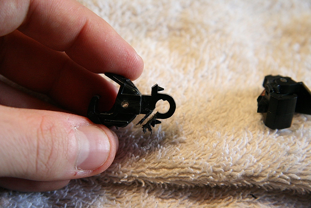
Once out, the Kadee #789 can be modified with a dremel and a file to drill a new hole and file it down so it fits through the front opening.
The Kadee uncoupler arm needs to be cut off smooth with the bottom of the coupler.
One benefit from this modification is the coupler assembly is now tight enough to keep from working it's way open after running the engine a while.
________________________________________________________________________________
01/11/05 MTH One Gauge Big Boy w/Protosound 2 - Protosound 3 - DCS - 70-3009-1 - 70-3026-1
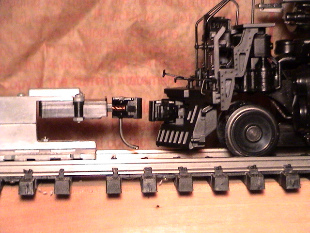
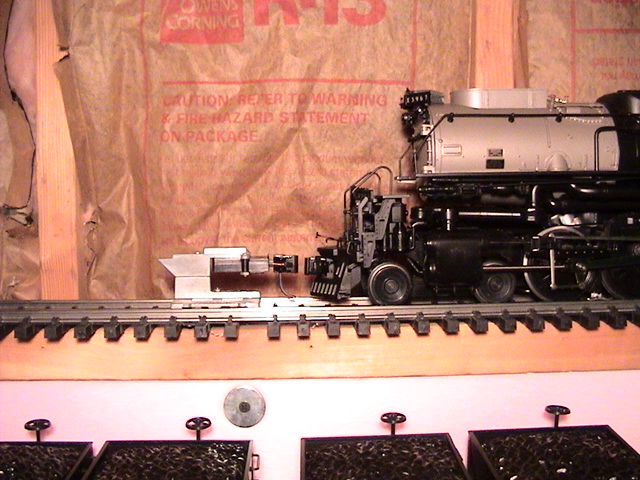
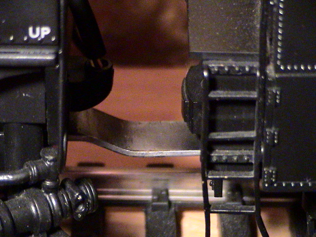
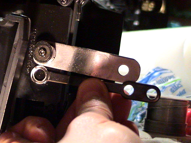
Challenger/Big Boy Drawbar upgrade: - (Applied to 2006 MTH One Gauge Big Boy)
I found that trying to back heavy, long trains up a steep grade would put cause the factory drawbar to tip down allowing the tender-drawbar peg to come out of the drawbar. To eliminate this issue and also shorten the distance between the engine and tender I made this custom drawbar out of scrap steel.
I replaced the stock spring with a few of the plastic washers that were included in the Kadee 881 adapter package. By using the washers instead of a spring, they help hold the drawbar in place when under heavy load backing up.
Here is the result.
|
|
|
|
|
|
|
|
|
|
|
|||
Drill bit sizes used:
|
||||
________________________________________________________________________________
08/21/04 MTH One Gauge Big Boy w/Protosound 2 - Protosound 3 - DCS - 70-3009-1 - 70-3026-1
Tender plug problem & repair: - (Applied to 2006 MTH One Gauge Big Boy)
See this link: Tender plug repair
________________________________________________________________________________
08/21/04 MTH One Gauge Big Boy w/Protosound 2 - Protosound 3 - DCS - 70-3009-1 - 70-3026-1
Charging the engine's PS2 on-board battery: - (Applied to 2006 MTH One Gauge Big Boy)
See this link: Charging engine PS2 battery
__________________________________________________________________________________
03/13/2011 MTH One Gauge Big Boy w/Protosound 2 - Protosound 3 - DCS - 70-3009-1 - 70-3026-1
Sound file update: (Corrects S01 softkey short whistle sound) - (Applied to 2006 MTH One Gauge Big Boy)
The MTH Big Boys as delivered from the factory had an incorrect sound for the S01 soft-key option. MTH has provided an updated file and now has it posted to their website for download.
See file located at: http://www.mthtrains.com/70-3009-1
Or download at this link: MTH Big Boy sound file - w/S01 update (11/01/2010)
Example of the incorrect S01 sound: (short whistle)
____________________________________________________________________________________________________________________
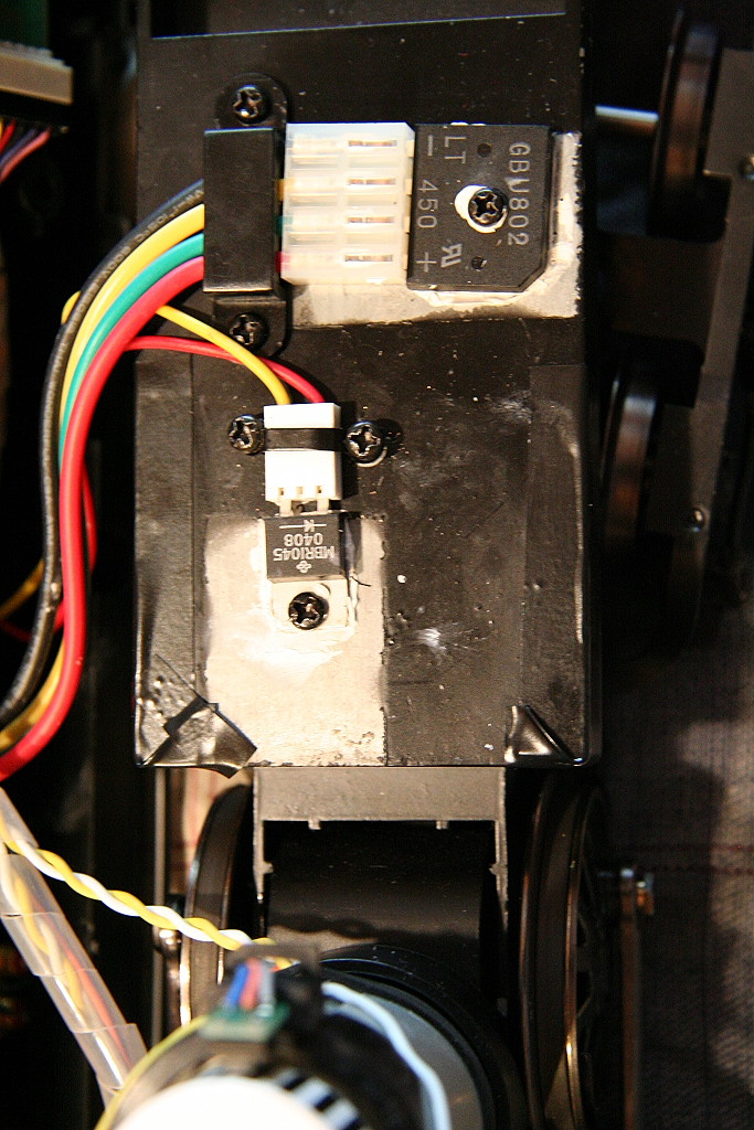
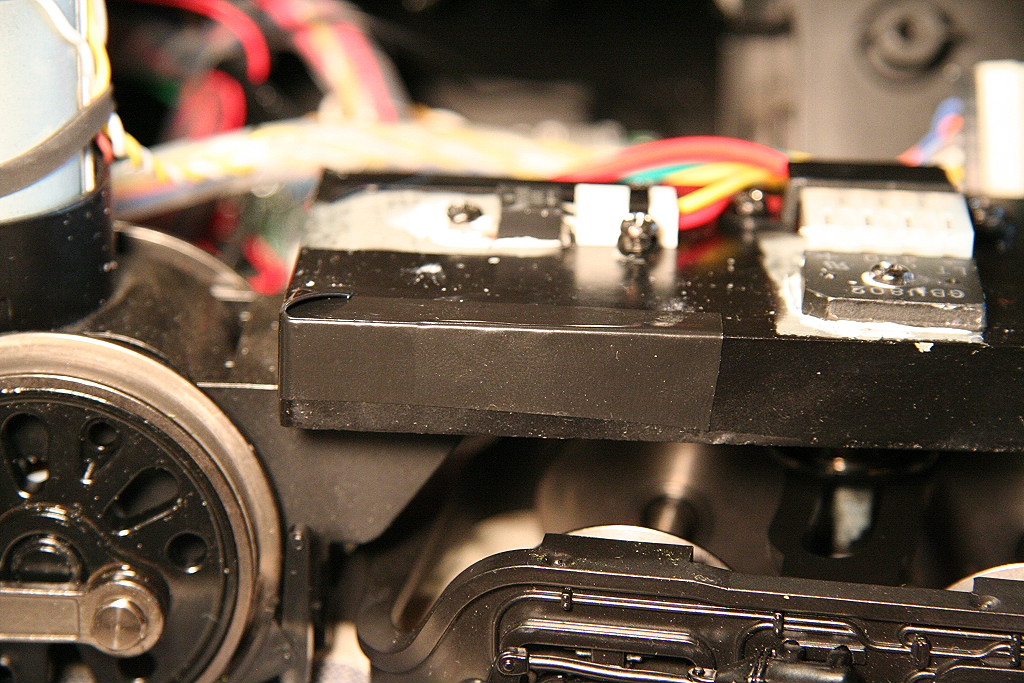
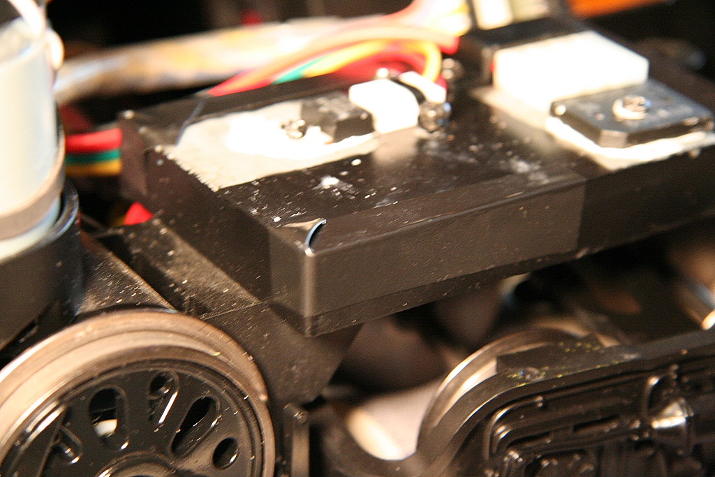
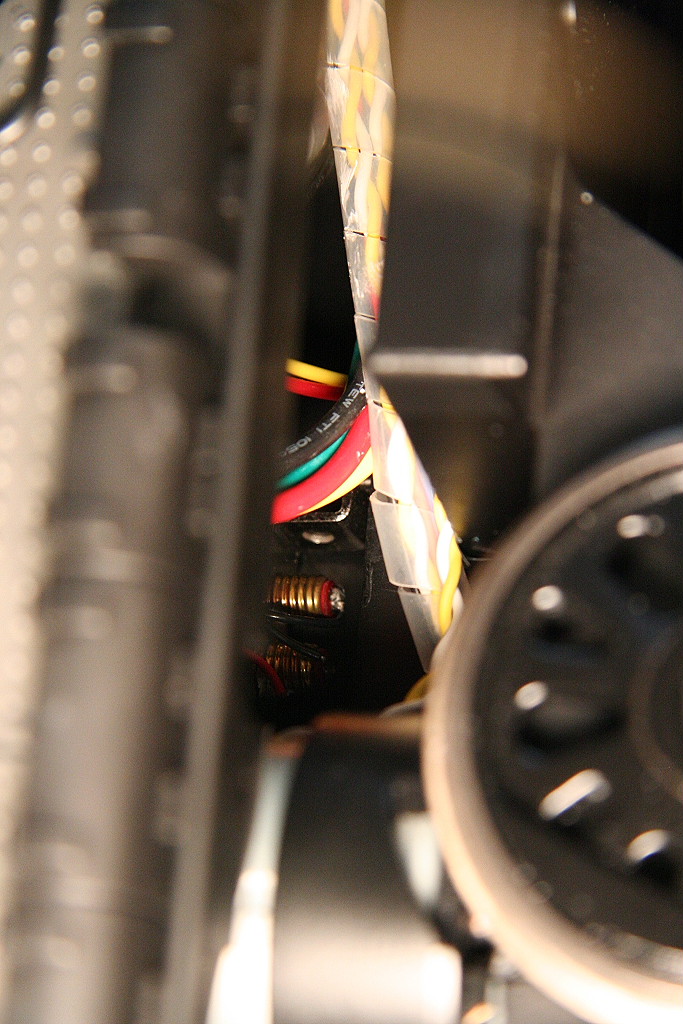
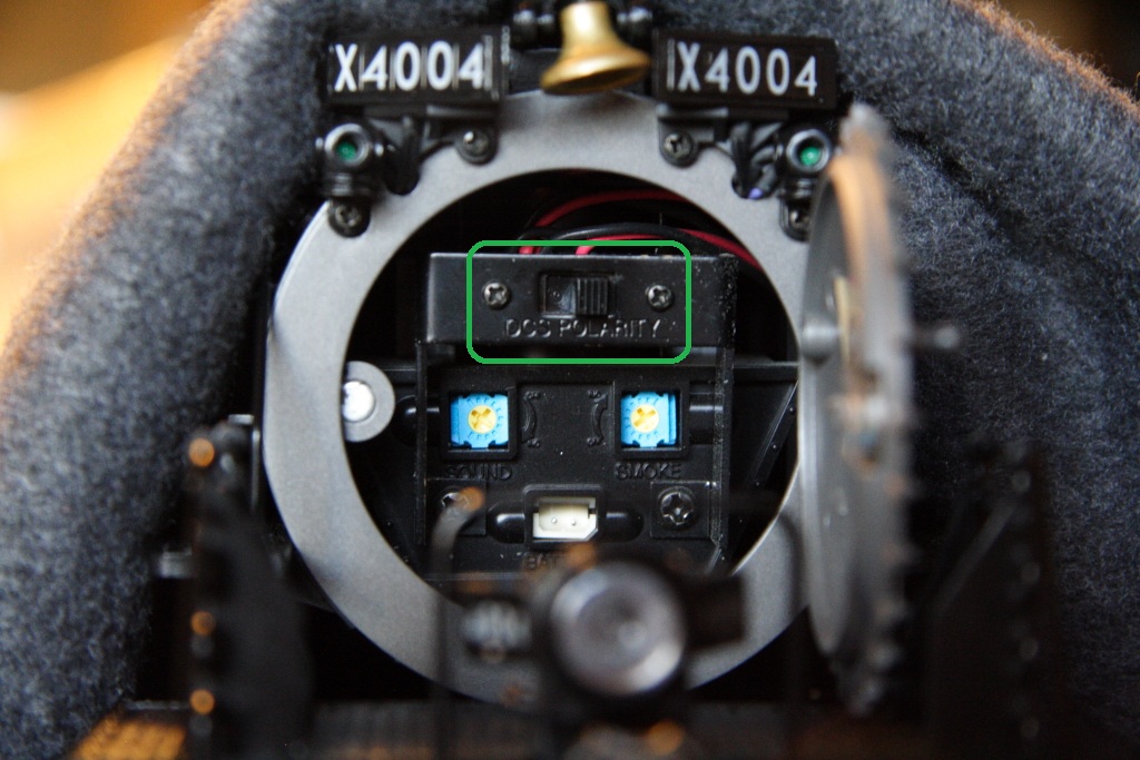
07/21/11 MTH One Gauge Big Boy w/Protosound 2 - Protosound 3 - DCS - 70-3009-1 - 70-3026-1
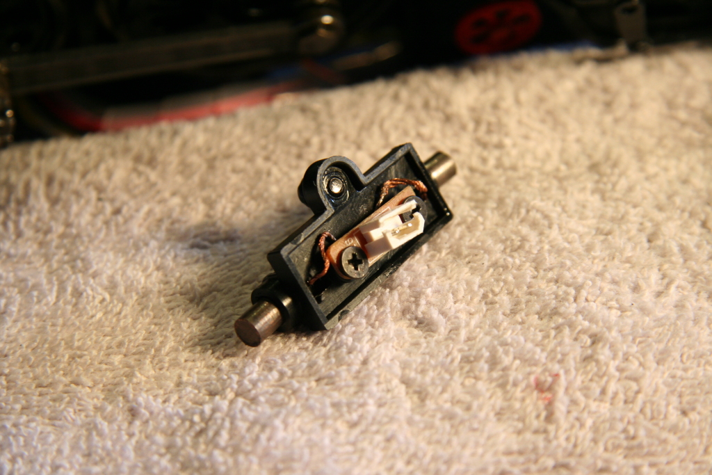
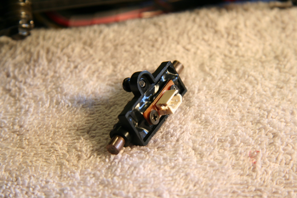
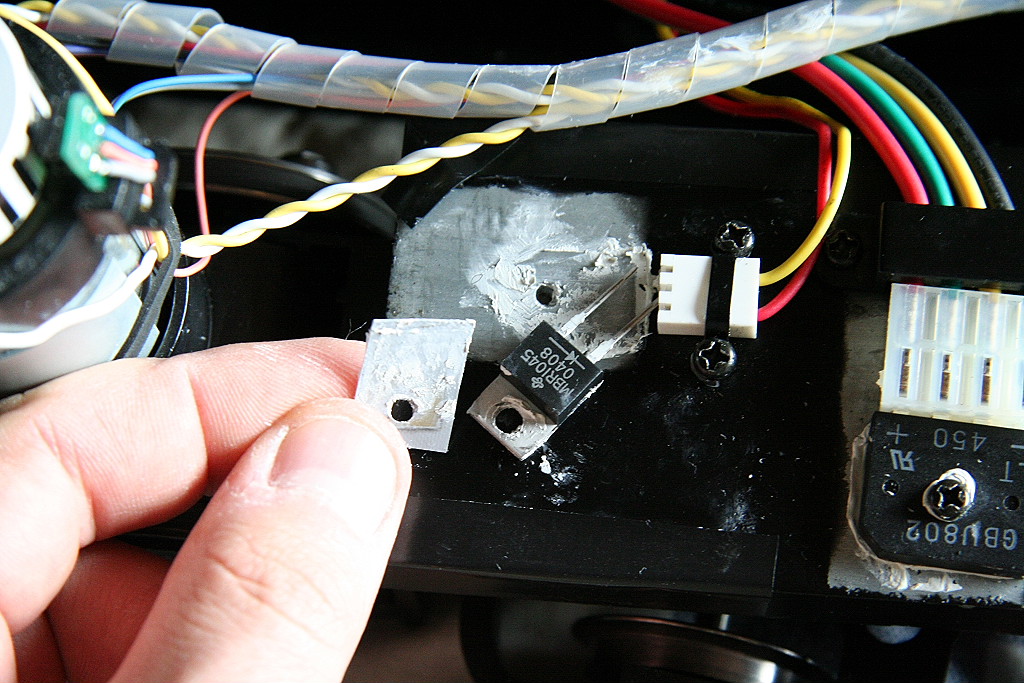
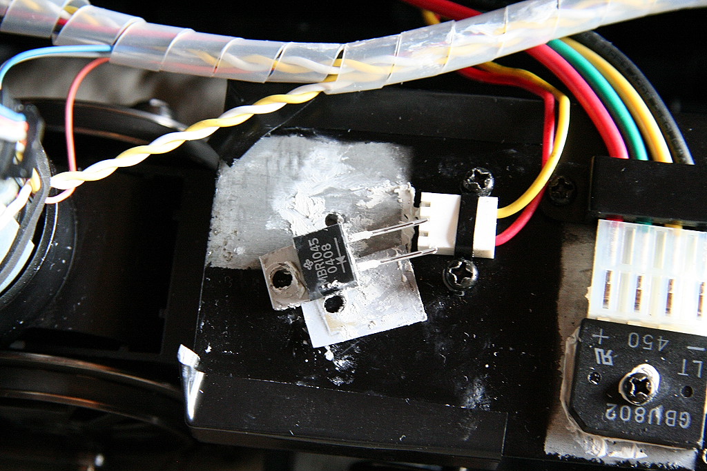
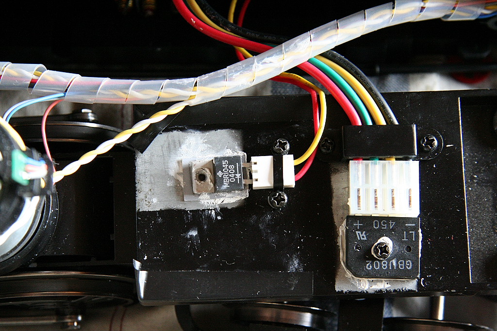
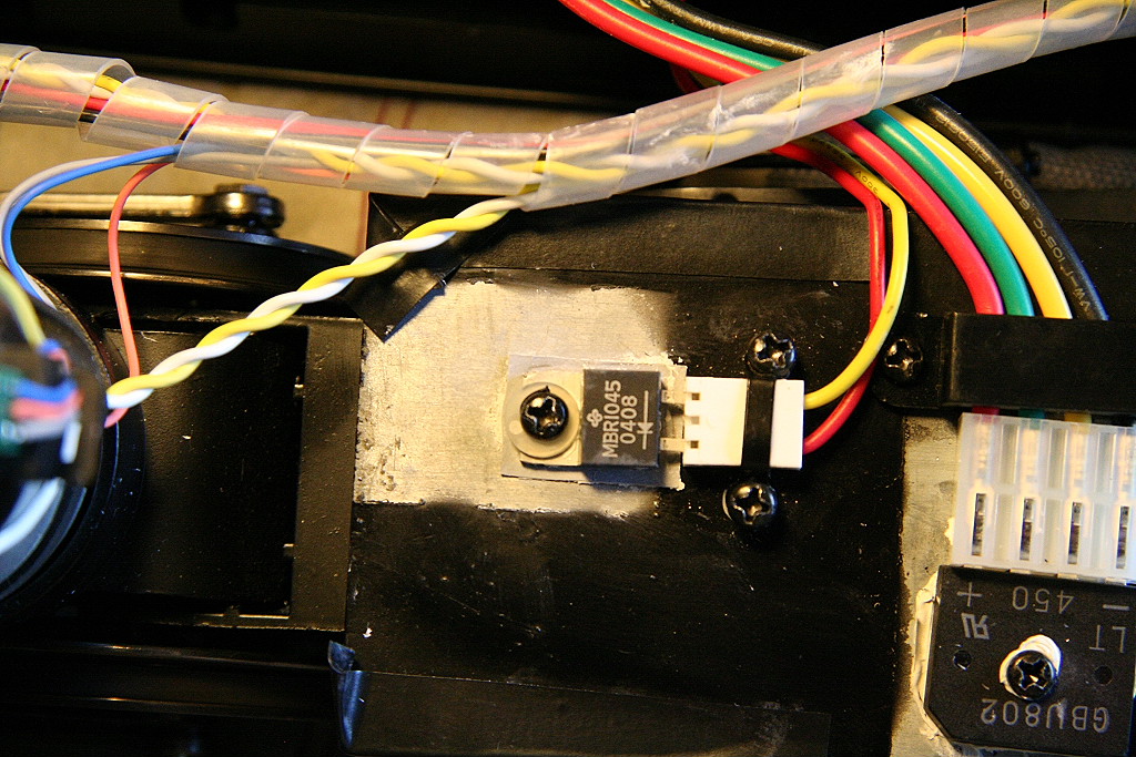
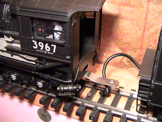
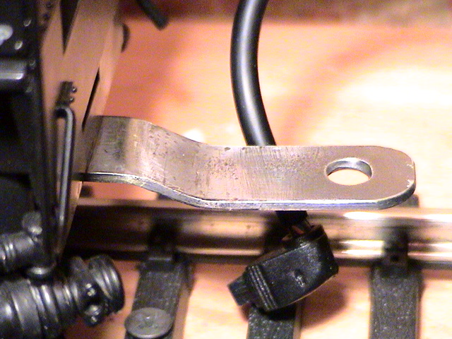
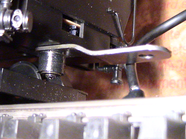
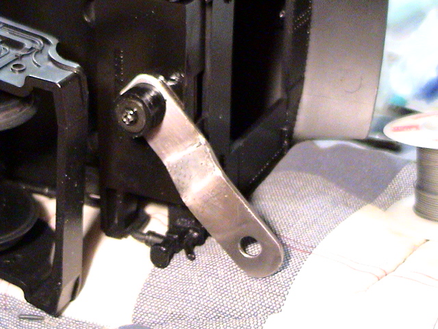
Polarity switch location: - (Applied to 2006 MTH One Gauge Big Boy)
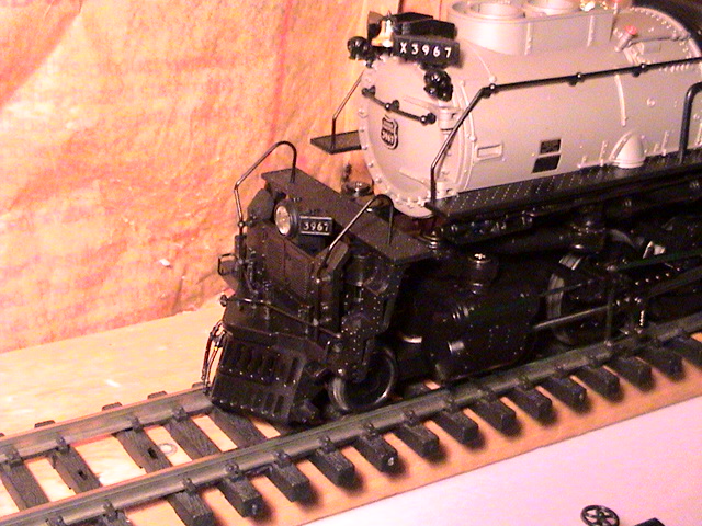
This is the location of the polarity switch on the Big Boy.
____________________________________________________________________________________________________________________
11/28/19
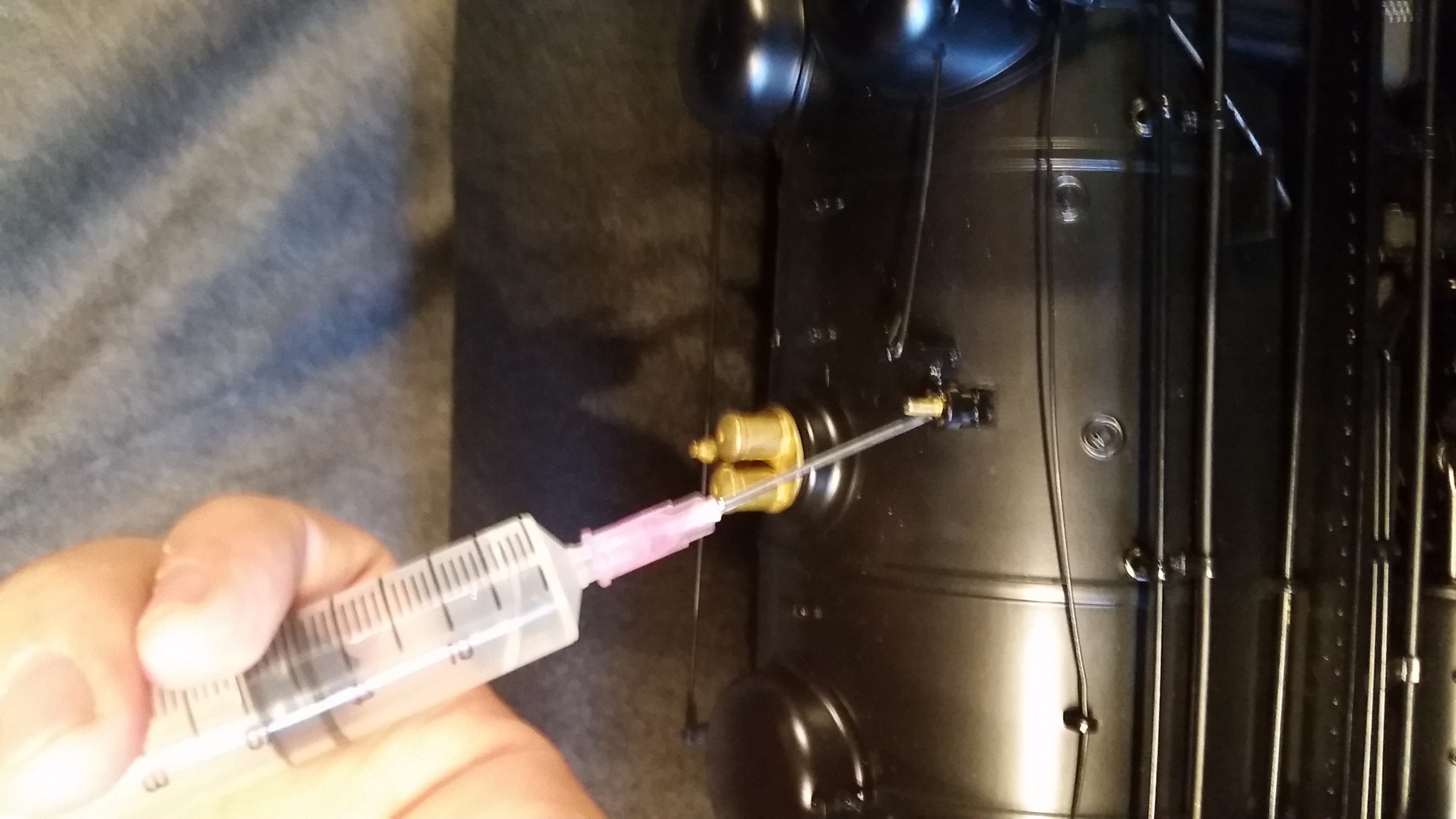
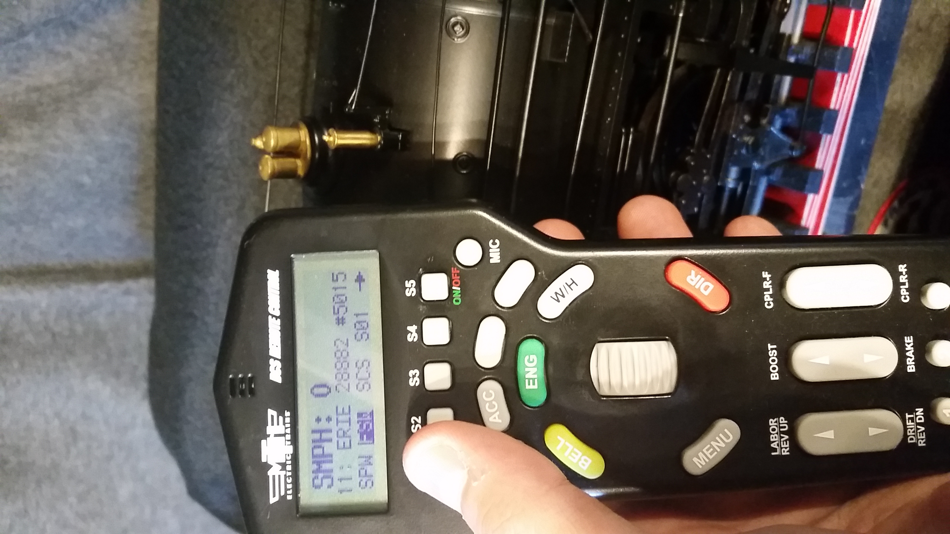
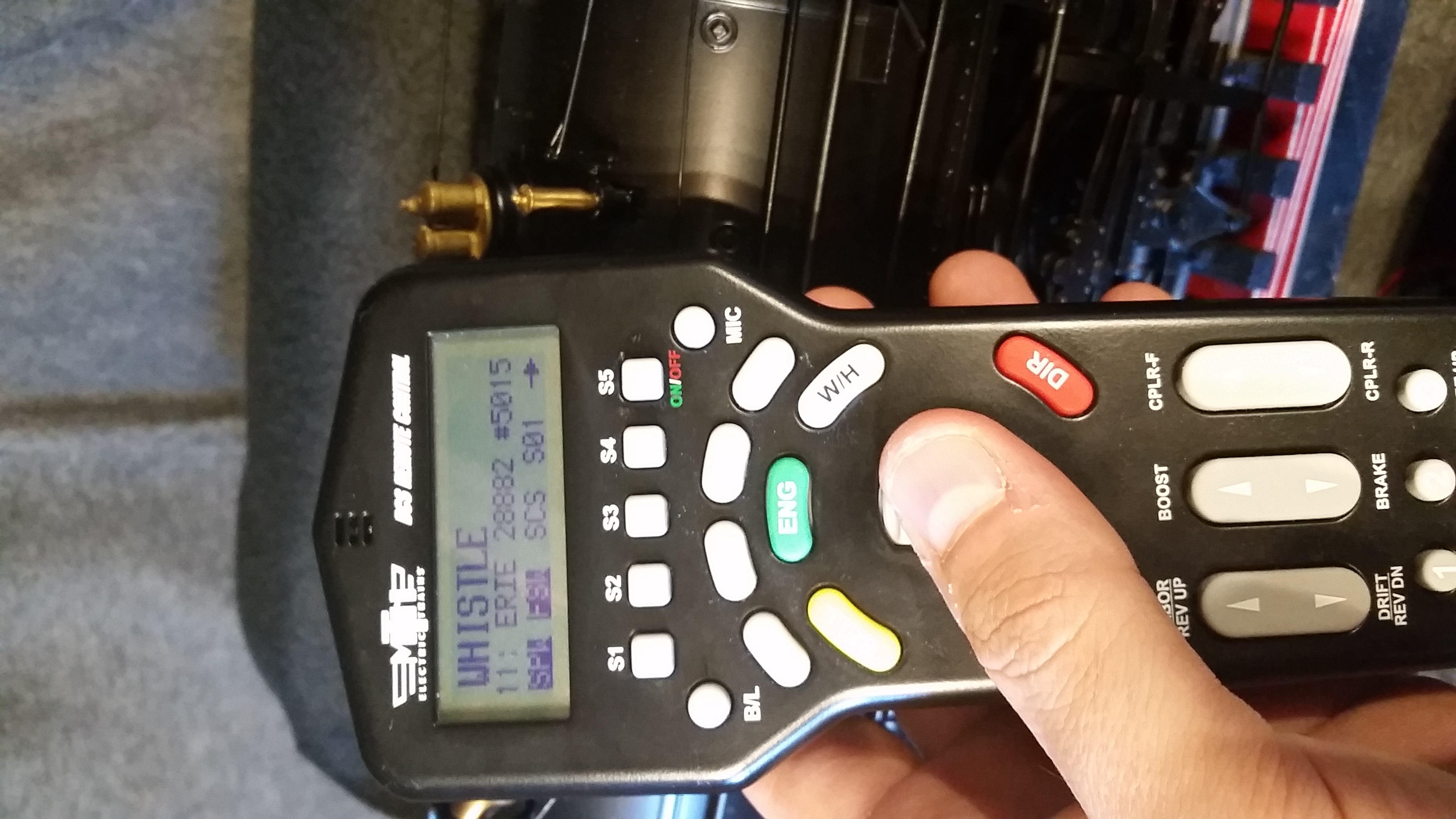
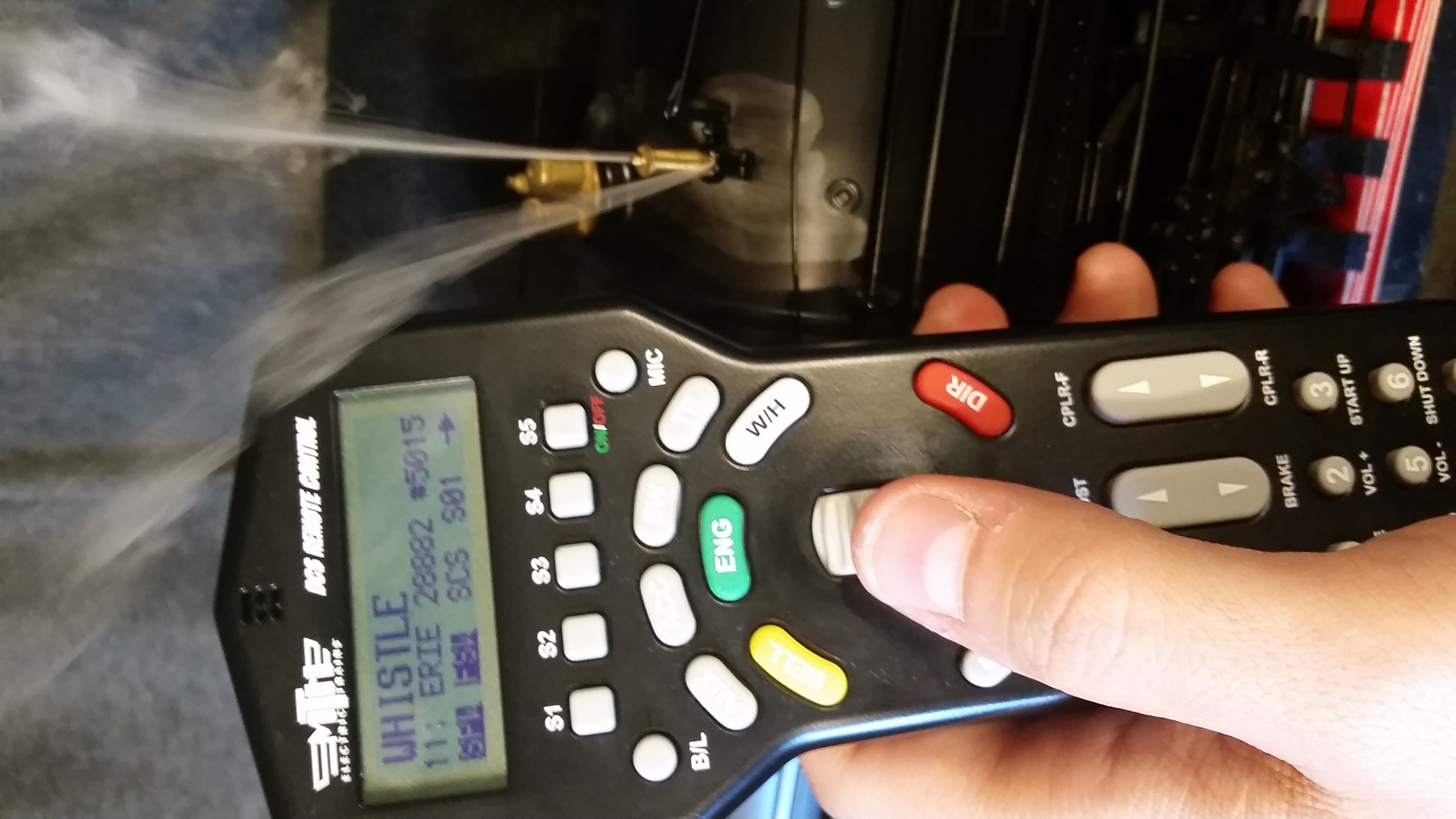
Smoking Whistle: Instructions on how to activate:
Do the following steps to activating the smoking whistle:
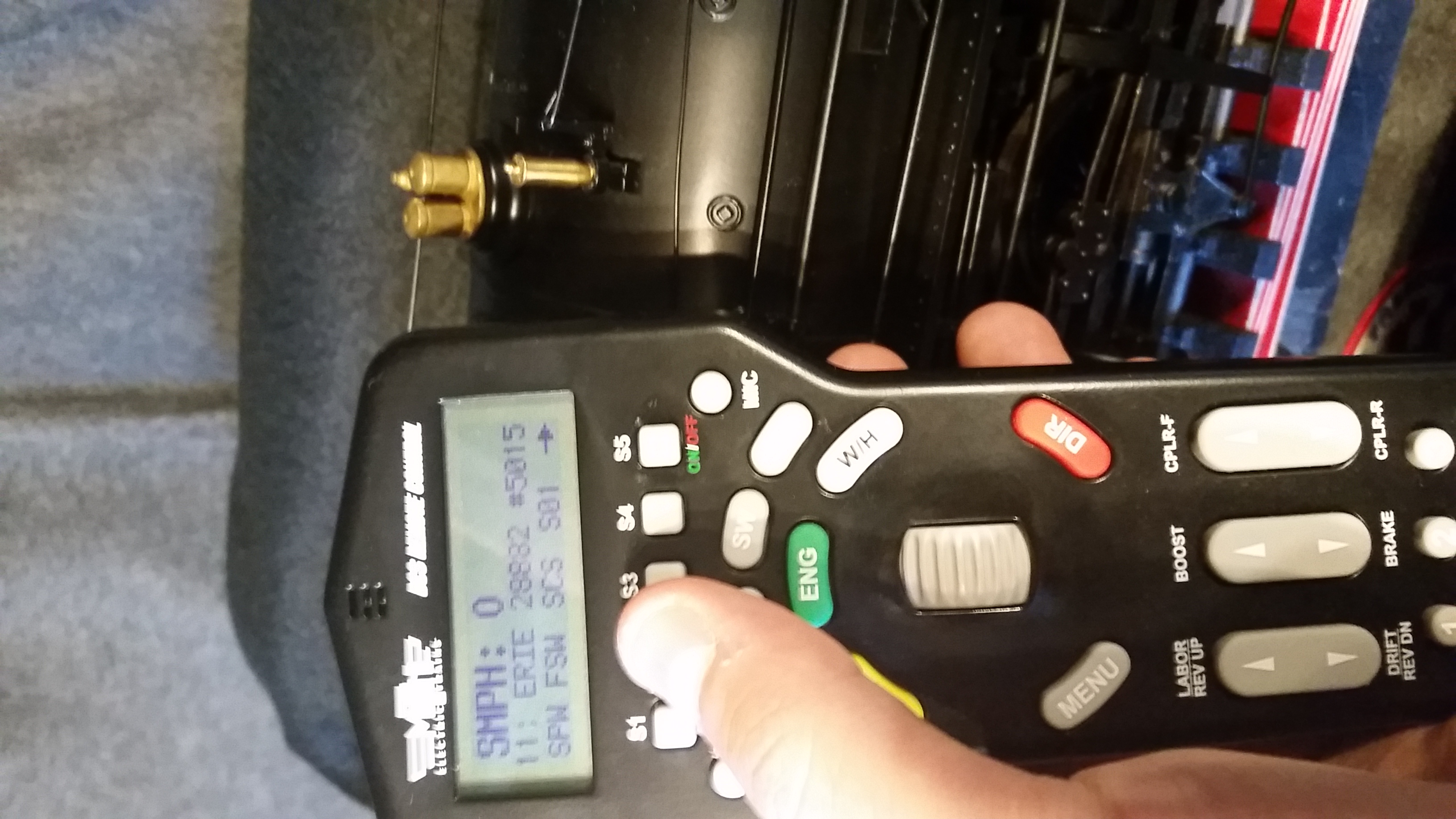
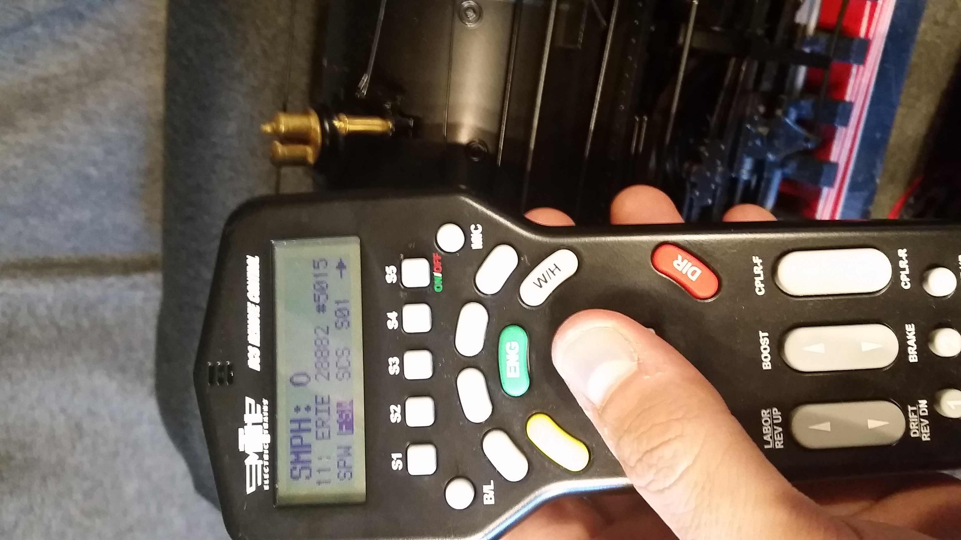
Note: If your DCS Remote and/or TIU has DCS software version of 3.11 or lower(older), these softkeys below will NOT appear on the remote screen. You must be using DCS v4.00 or higher in order to see the softkeys. Once you update Remote & TIU with updated version, you will need to delete engine from remote and re-add to see the softkeys. If your engine does not come with a smoking whistle, FSW will not be displayed on your remote (SPW may be displayed if engine has playable whistle feature).
Using DCS Remote:
- Step 1: Add 6 drops of smoke fluid into the whistle opening. (If needed)
- Step 2a: Press "S2" (FSW) button - (This turns on the smoke whistle heater)
- (Note: You may need to scroll the softkey list with "S5" button to display SPW and FSW labels)
- Step 2b: Turn thumbwheel down - (This updates the screen to confirm FSW is highlighted/activated)
- Step 3a: Press "S1" (SPW) button - (This turns on the Whistle Quill feature)
- Step 3b: Turn thumbwheel down - (This updates the screen to confirm SPW is highlighted/activated)
- Step 4: Rotate the thumbwheel up to activate/increase whistle (Three steps of quill are available). Rotate thumbwheel down to deactivate/decrease whistle.
- (Note: If you see smoke coming out the bottom of the boiler and not the top, blow in the top of the whistle hole to clear any fluid bubbles and retry)

Step 1:

Step 2a:

Step 2b:

Step 3a:

Step 3b:

Step 4:
Using WIU w/Wifi and DCS App:
- Step 1: Add 6 drops of smoke fluid into the whistle opening. (If needed)
- Step 2: Go to 3rd screen on DCS App and scroll down and activate "Playable Whistle"
- Step 3: Activate "Whistle Smoke"
- Step 4: Go back to main engine control screen with speed dial and pull on the whistle cord and smoke will come out the whistle.
____________________________________________________________________________________________________________________
08/13/19 MTH One Gauge Big Boy w/Protosound 2 - Protosound 3 - DCS - 70-3009-1 - 70-3026-1
Packing - 2015/2017/2018 Models:
See below for packaging reference photos.
***It is CRITICAL that all bolts and posts be used when shipping this engine! Do not discard or attempt to ship without the original mounting hardware!***w/Protosound 2 - Protosound 3 - DCS - 70-3009-1 - 70-3026-1
***Click this link for photos of 2015/2017/2018 packaging***
____________________________________________________________________________________________________________________
04/21/22 MTH One Gauge Big Boy w/Protosound 2 - Protosound 3 - DCS - 70-3009-1 - 70-3026-1
See below for packaging reference photos.
***It is CRITICAL that all bolts and posts be used when shipping this engine! Do not discard or attempt to ship without the original mounting hardware!***w/Protosound 2 - Protosound 3 - DCS - 70-3009-1 - 70-3026-1
***Click this link for photos of 2020/2022 packaging***
__________________________________________________________________________________
Return to Garden Railroad Modification page.