|
08/21/04
MTH Challenger front driver binding at slow speed fix:
I found at slow speeds (1-2 SMPH), my Challenger's front engine set had a slight bind in the forward direction. (but not reverse). The cause (as noted in my write-up on the binding on some Big Boys Driveline binding / not running smooth (Drivers out of quarter) ) is a slight out of quarter situation in the driver sets.
Because the Challenger driver sets can't be easily removed from the frame without modifications, my solution was to shim the connecting rod holes in such a way as to alleviate the problem.
*************************
Detail explanation as to exactly what is happening to cause the hesitation/binding:
If the binding is happening when moving forward as in this case, the left side connecting rods were not pulling the first driver around far enough to keep the first and second drivers in proper sync. This was due to them being slightly out of quarter and the excess play between the connecting rods and the driver connecting rod pins. The second driver was a little behind the third (the third driver is driving the whole set) and the first driver was that much farther behind and out of sync.
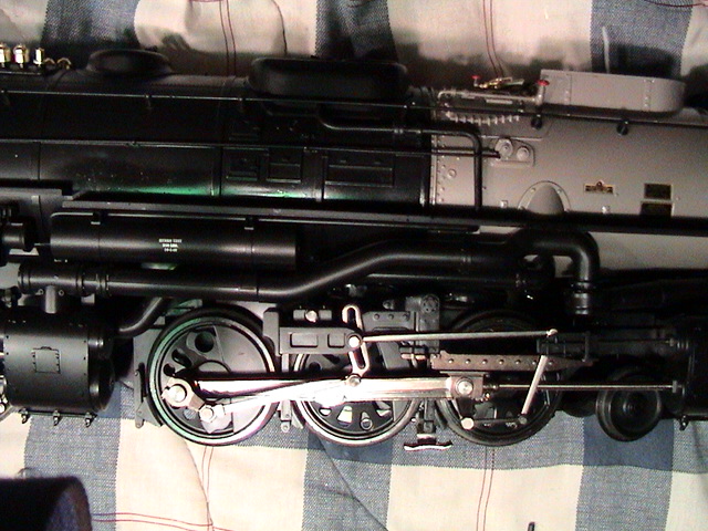
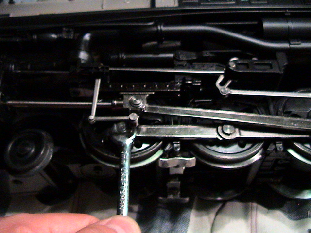
The front drivers would bind as the left side connecting rod pins (drivers rotating counterclockwise) reached the 4 or 5 o'clock position. To see this with the engine off the tracks, you can pinch the first driver with your fingers with one hand to create simulated resistance (as it would see on the tracks) then turned the assembly (counterclockwise/forward) with the third driver with the other hand. You can feel the drivers binding. In looking at the right side of the front engine, you would be able to see the connecting rod between the first and second driver binding. This is because the first driver (connecting rod pin) hasn't been pulled around far enough by the left side connecting rods. The actual bind point is because the second and third right side connecting rods are beginning to move forward while the first driver's pin is still on it's way up. This series of events is causing the front connecting rod to ram into the first driver pin causing the binding.
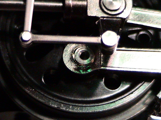
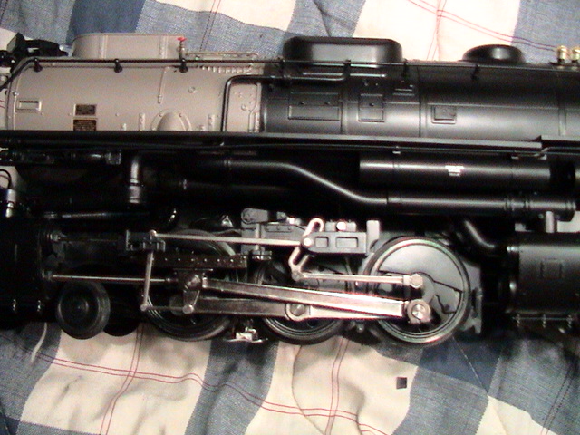
Left side picture of the front drivers:
|
||||
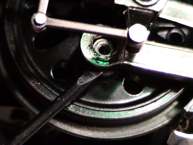
Right side picture of the front drivers:
|
||||
**********************************
Solution:
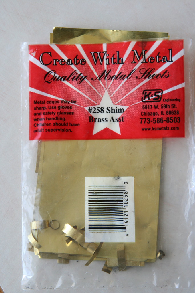
My solution was to purchase a package of brass sheets in various thicknesses and use them to reduce the play between the connecting rods and the connecting rod driver pin by making a spacer bushing. (Note: This shim solution will likely only work if the drivers aren't too far out of quarter. If they are too far out of spec, they will need to be manually quartered which may require you send the engine back to MTH.)
|
|
|
||
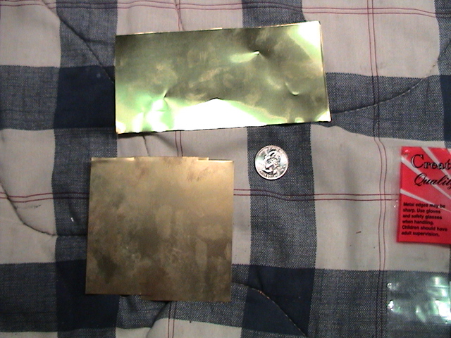
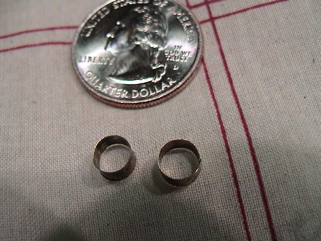
Using scissors, I cut a strip from the thickest sheet and looped it to create a spacer bushing. Make sure the bushing isn't taller than the width of the connecting rods. (Wrapping the strip around a properly sized screw driver helps when trying to make it round.) I then cut a strip of a medium thickness sheet and looped it to create another spacer bushing. I used the thicker spacer bushing on the: first driver left (fireman's) side, and both second drivers. I added the second medium thickness bushing to both second drivers. By adding the second medium thickness bushing, this made it so there is very little slop between the connecting rods on the second drivers and the connecting rod driver pins.
I found out that the second inner bushing was needed through much trial and error and the fact there was still a lot of slop in the second driver pin even after the first thick bushing was made.
|
||||
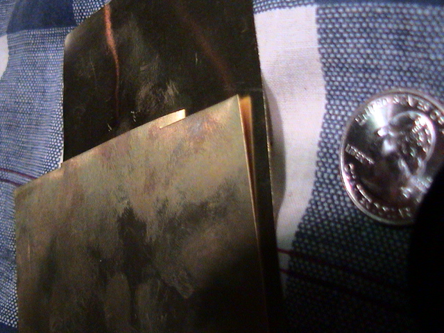
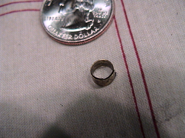
Below is a picture of the two bushings combined before they were inserted onto each of the second drivers. The thinner bushing is inside the thicker one.
|
||||
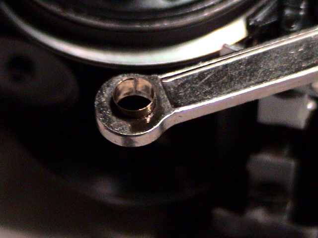
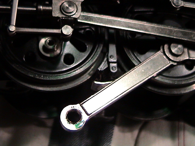
Next, insert the bushing into the connecting rod hole. In this case, the single thick bushing.
|
|
|
|
|
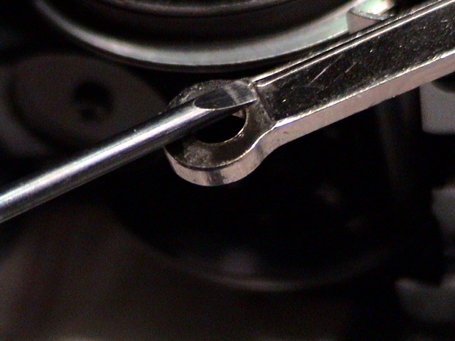
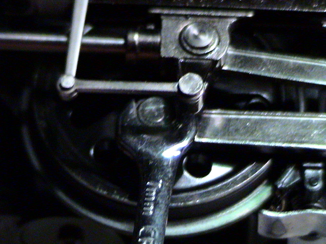
Then fit the connecting rod onto the driver connecting rod driver pin and press down on the connecting rod and the bushing with your thumb. I jiggled the bushing and rods with my thumb until the bushing conformed to the curvature of the connecting rod pin.
|
|
|
|
|
Repeat the above steps for both second drivers using the double bushing.
____________________________________________________________________
Return to Garden Railroad Modification page.