MTH: GS-4/GS-2 - Repair/Modifications page:
(Click here for MTH: GS4 (Daylight) - GS4 (Freedom) - GS2 - Photo & Video Page)
MTH One Gauge Catalogs:
Model Overview:
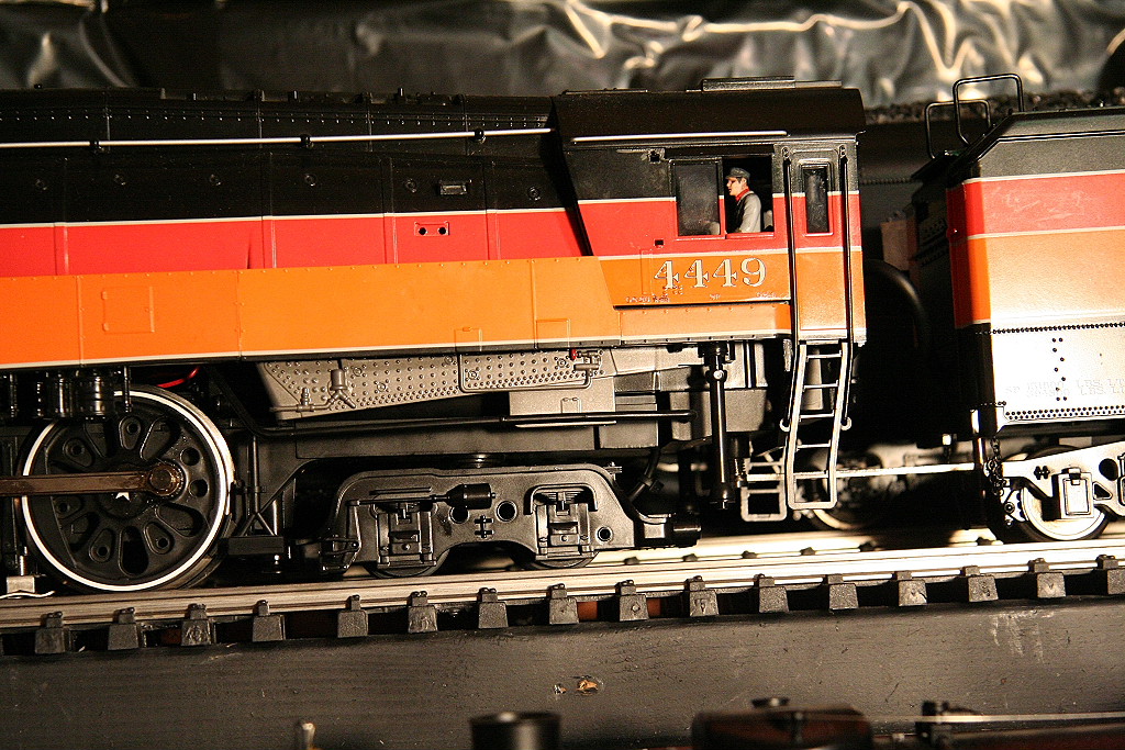
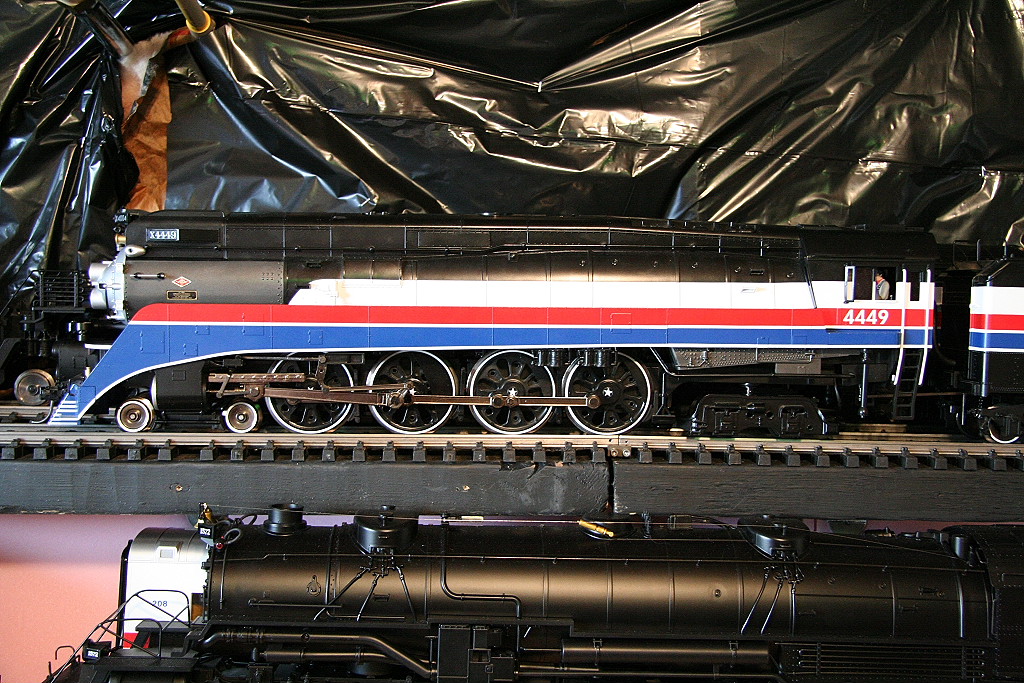
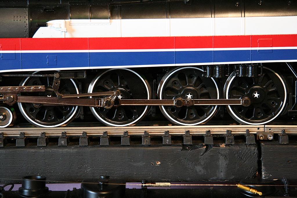
The GS-4/ GS-2 was MTH's second set of new steam engines produced.
________________________________________________________________________________
MTH GS4/GS2 Repair/Modifications:
Modifications/Topics list:
MTH - GS-4/GS-2 (Repair page):
________________________________________________________________________________
07/21/11
MTH GS4 (Daylight & Freedom Train) - Motor Cooling Modifications:
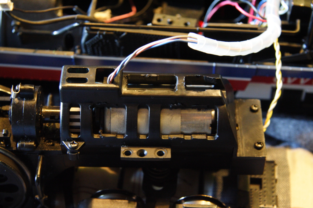
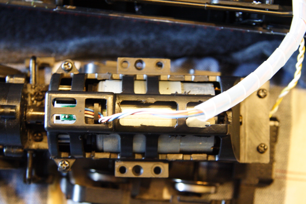
If you run your GS-4 under very heavy load conditions, up steep grades and at higher speeds for longer periods of time the motor may get overly hot. This is in part due to the fact the motor on the engine is mostly encased in plastic which does not allow the motor to breathe and dissipate heat.
To resolve this, you will want drill breather holes and cut off excess plastic from around the motor.
You will first want to drop the drive train from under the boiler. There is one screw at the front above leading truck, and four at the back above the trailing truck. Once the drive train is separated, remove the screws holding the top motor shell. Next unscrew the two screws from the bottom holding the motor in place and remove the motor. Next, cut out some of the excess shell supports and drill out large holes in the bottom of the engine as seen in the photos. Reassemble the engine and you're done.
Here are some post modification photos:
|
|
|
||
Post modifications, the motor will stay nice and cool.
________________________________________________________________________________
08/21/04
See this link: Tender plug repair
___________________________________________________________________________________________________________________
01/27/07
MTH GS4 (Daylight & Freedom Train) - Adding additional power pickups:
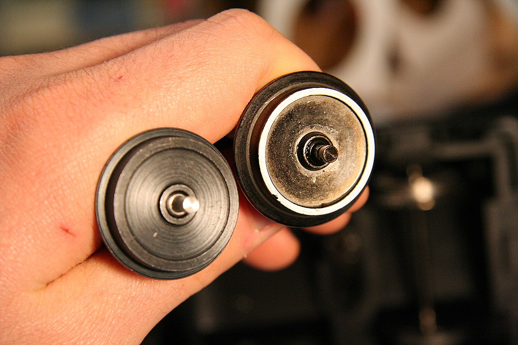
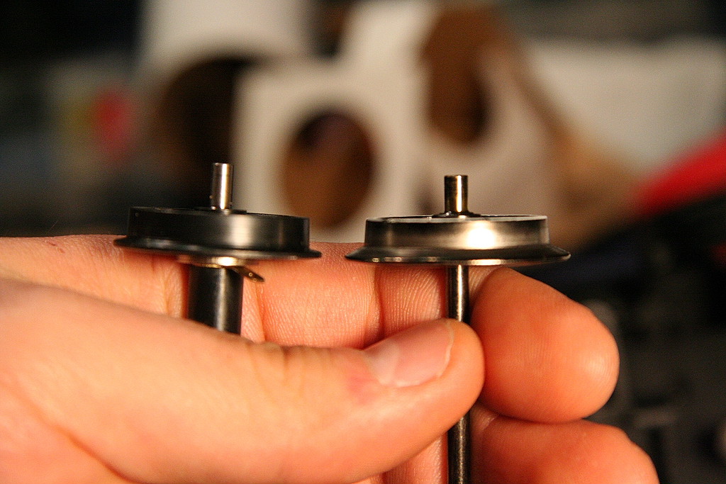
Replacing the GS-4 Trailing truck wheels with Accucraft 1:32 Ball Bearing power pickup wheels
___________________________________________________________________________________________________________
Different engines and trailing truck wheel replacement info:
MTH Challenger/BB lead truck wheels=1.07-1.08
(Replacement would be Accucraft BB 1:32=1.03-1.04 BUT I don't think they are
really feasible with the axle shroud they look to have.)
MTH Challenger/BB trailing truck wheels=1.25 (Replacement would be LBG
Ball Bearing wheel=1.22 OR Accucraft BB 1:20.3=1.182 OR Aristo BB blackened
wheels=1.175)
MTH GS-4 or GS-2 lead truck wheels=.968-.978 (Replacement is unknown.)
MTH GS-4 or GS-2 trailing truck & tender wheels=1.04-1.05 (Replacement
would be Accucraft BB 1:32=1.03-1.04 and should work great. Axle end length
would be be the only outstanding question.)
_________________________________________________________________________________________________________________________
For the GS-4, the Accucraft 1:32 Ball Bearing wheels could be used as a direct replacement as they are identical in wheel diameter.
The axle ends need to be filed down in order to fit and may require one or two small washers on the axle end on each side to limit the side to side play of the truck frame on the axles.
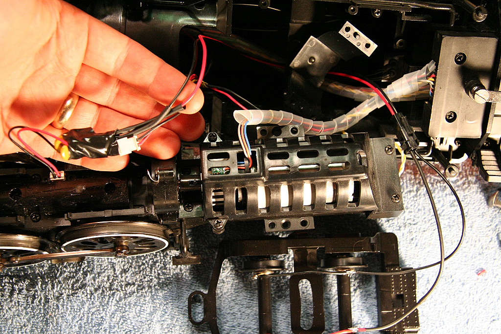
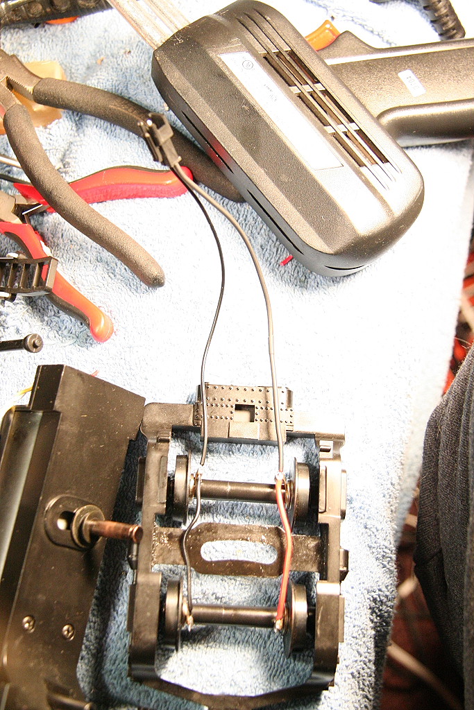
The photos below show what was done. I simply soldered wires (with a detachable connector -> http://www.allelectronics.com/cgi-bin/item/CON-240/189/2-CONDUCTOR_LOCKING_CONNECTORS_W__LEADS_.html ) to the ball bearing power pickup tabs then tapped into the left and right power pickup wires coming from the drive block.
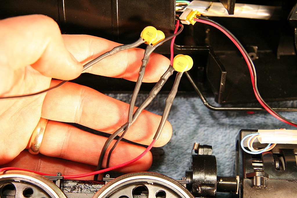
To protect against shorts, I added three of these auto-resetting solid state fuses in each wire lead: http://www.allelectronics.com/cgi-bin/item/RXE-065/search/RESETTABLE_CIRCUIT_PROTECTOR_0.65_-_1.3_AMP_.html
|
|
|
|
|
|
|
|
|
|
|
|
|
|
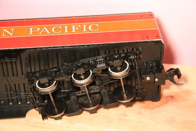
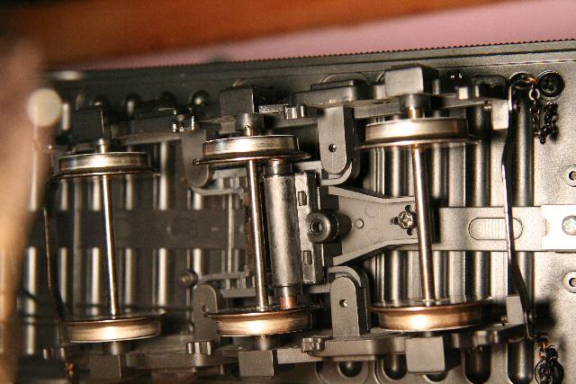
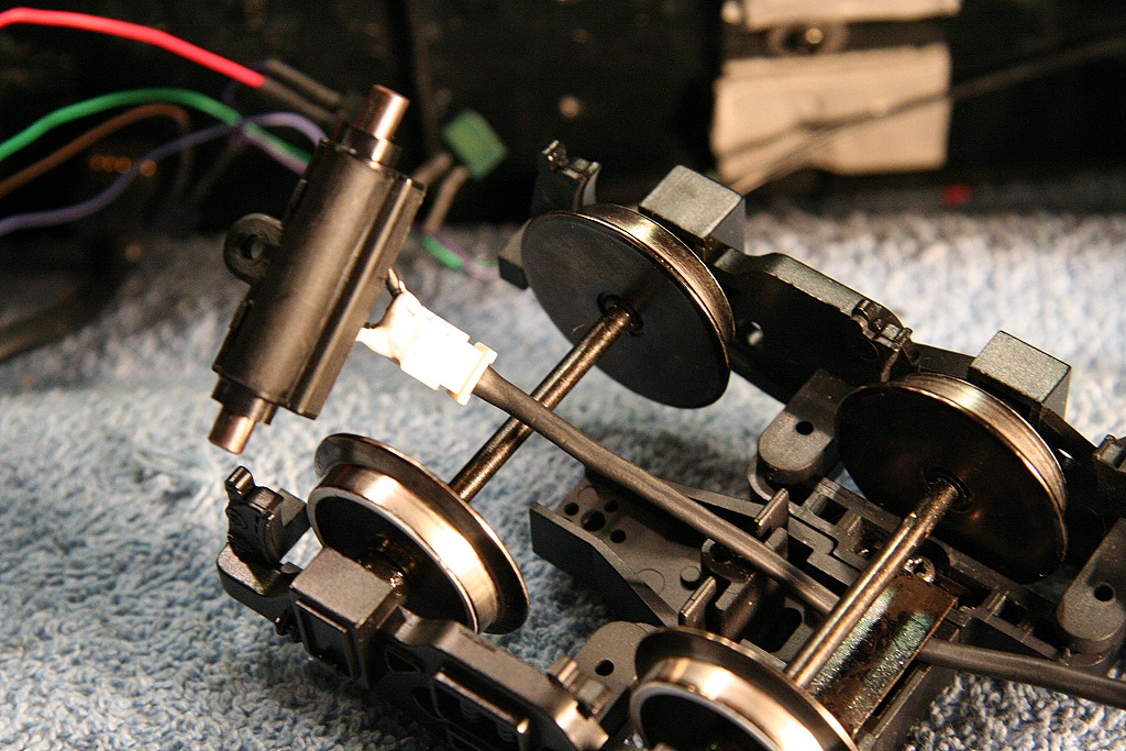
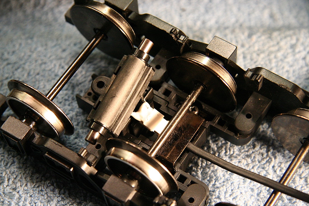
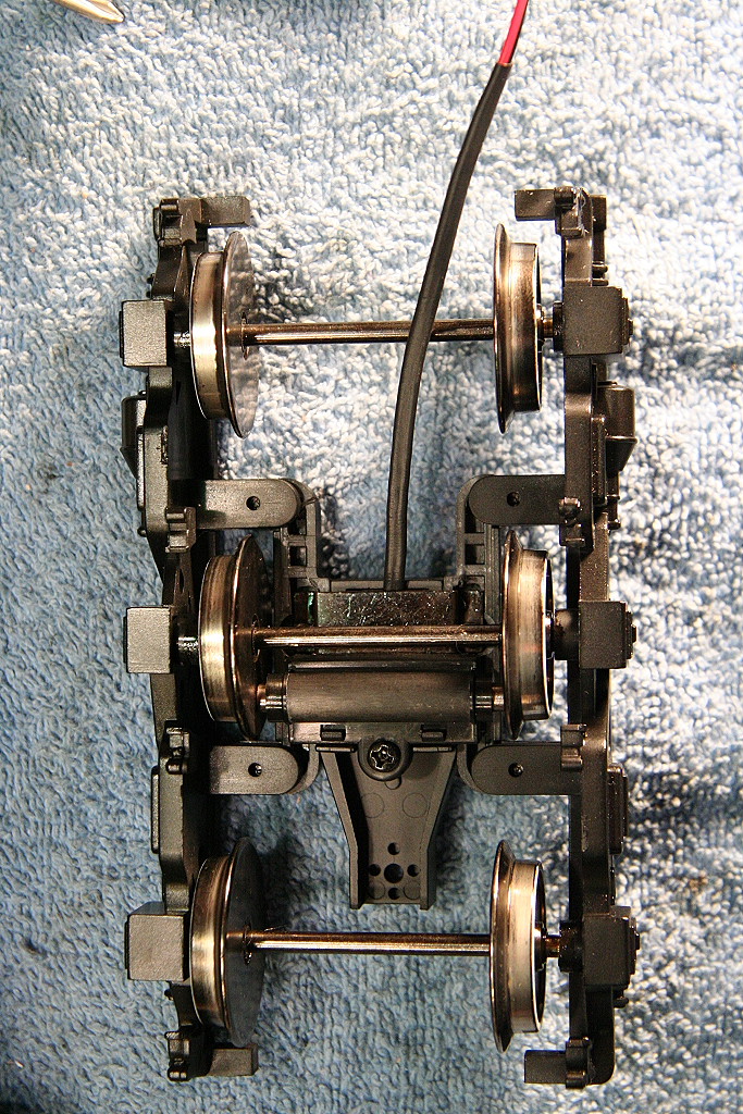
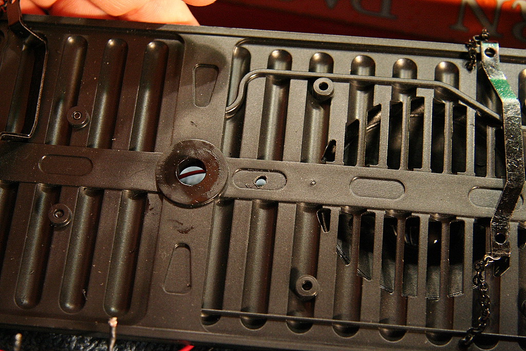
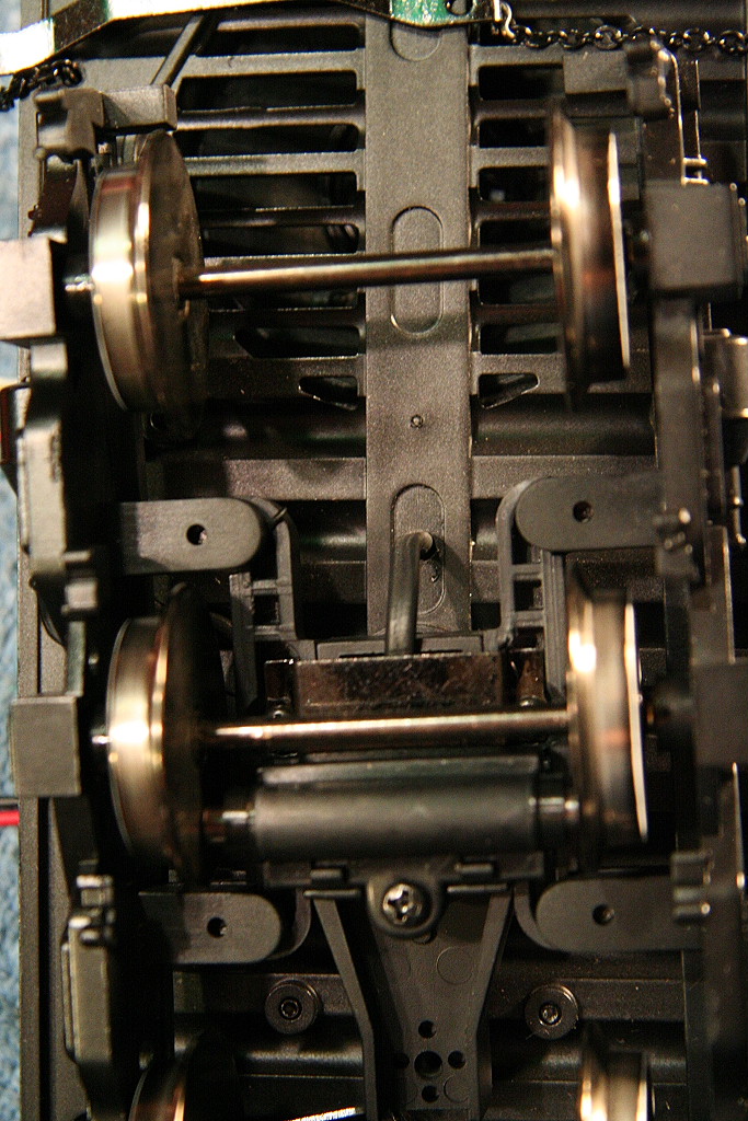
Installing MTH inside power pickup assemblies on the tender trucks
Each MTH One Gauge GS-4 and Hudson tender is already setup to accept 1 MTH wheel power pickup assembly. The following pictures show how I installed mine.
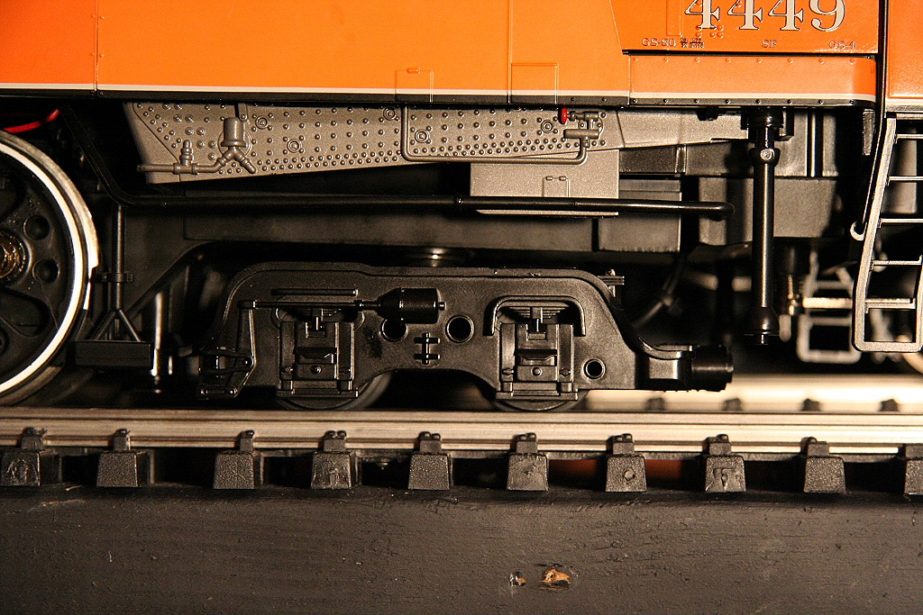
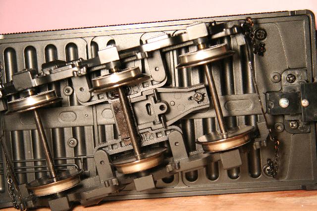
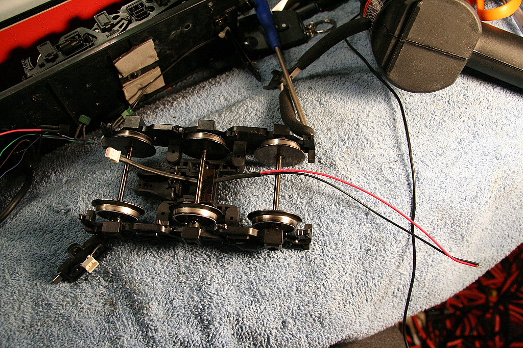
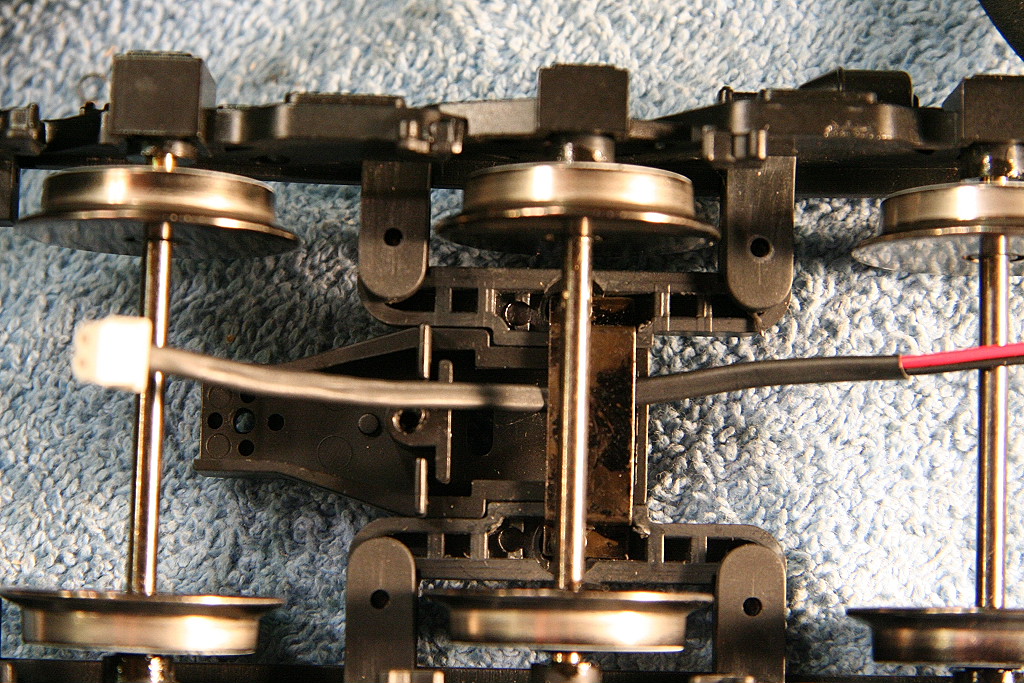
First, this is what the trucks look like and where the pickup assembly goes:
|
|
|
|
|
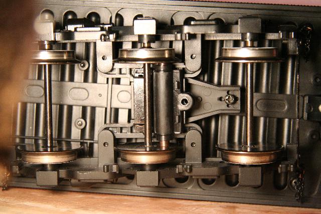
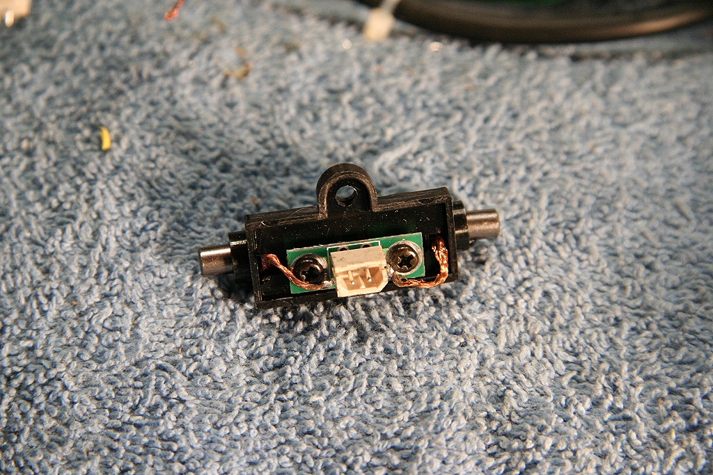
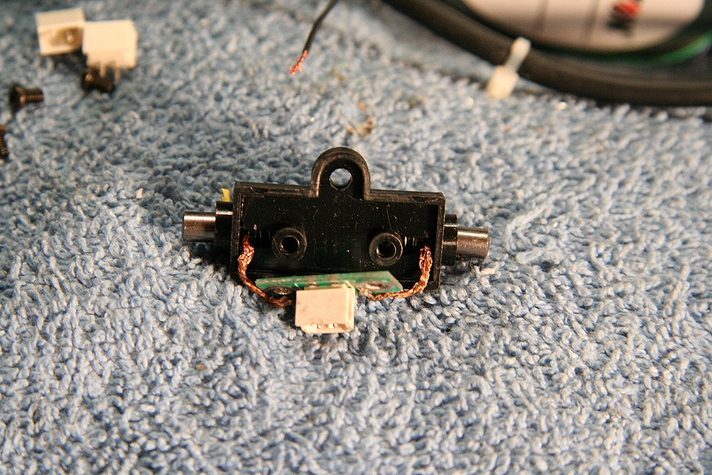
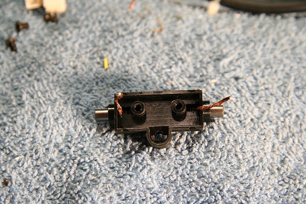
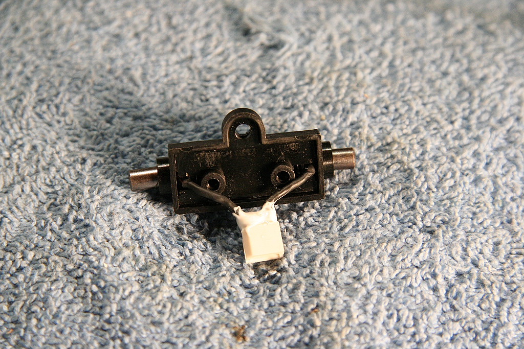
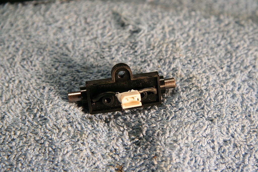
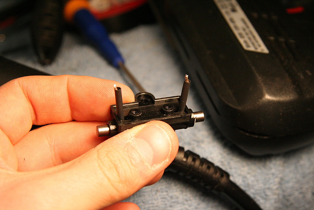
Below shows the modifications made to the pickup assembly in order to fit correctly and also be removable later to allow easy replacement. The white substance on the back of the connector on the wheel pickup assembly is hot glue to ensure the wires stay put and don't bend and break off in the future.
(Note: If you would like to order these parts please
contact me at:
 )
)
|
|
|
|
|
|
|
|
|
|
|
|
||
I next drilled a hole for the new pickup wires to route them in the tender.
|
||||||
Here is the new assembly installed.
|
|
|||||
To transfer power to the engine I recommend adding a dedicated pair of wires with new 2 pin connector between engine and tender. This is so you don't damage wires in the factory harness in the event of a short. Inside the engine will need to tap the correct Red and Black wires from the track power pickups. (no pictures available at this time)
Here is the result (temporary setup with the sliders removed) I do recommend keeping the power pickup sliders in addition to any additional wheel power pickups added as you simply can't get any better or more reliable power pickup than from pickup shoe sliders.
|
|
|
||
___________________________________________________________________________________________________________________
11/5/2014
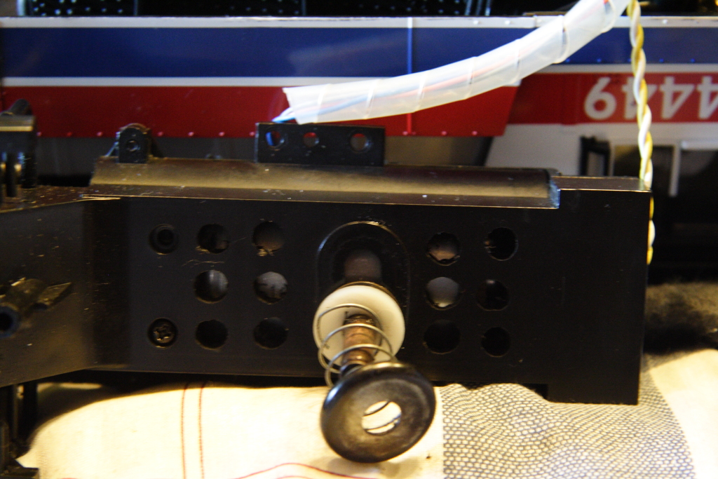
Sliders not staying against the rail / weak slider springs:
The original release GS-2 / 4 models all had slider springs that were significantly weaker in strength than all the other One Gauge steam production. These weak springs result in the sliders not having enough downward force on them to ensure they remain in contact with the rail in all conditions. If the slider has a slight bit of resistance in it's distance of travel in the assembly, it can get stuck up away from the rail. The way to fix this is to replace the four slider springs with stronger ones. I have these replacement springs available and in-stock.
Note, this is the only MTH One Gauge engine I've seen with springs that were too weak, all others I've seen have been fine.
___________________________________________________________________________________________________________________
03/04/2009
Power Pickup Sliders getting caught in switch frogs (Particularly #6 switches)
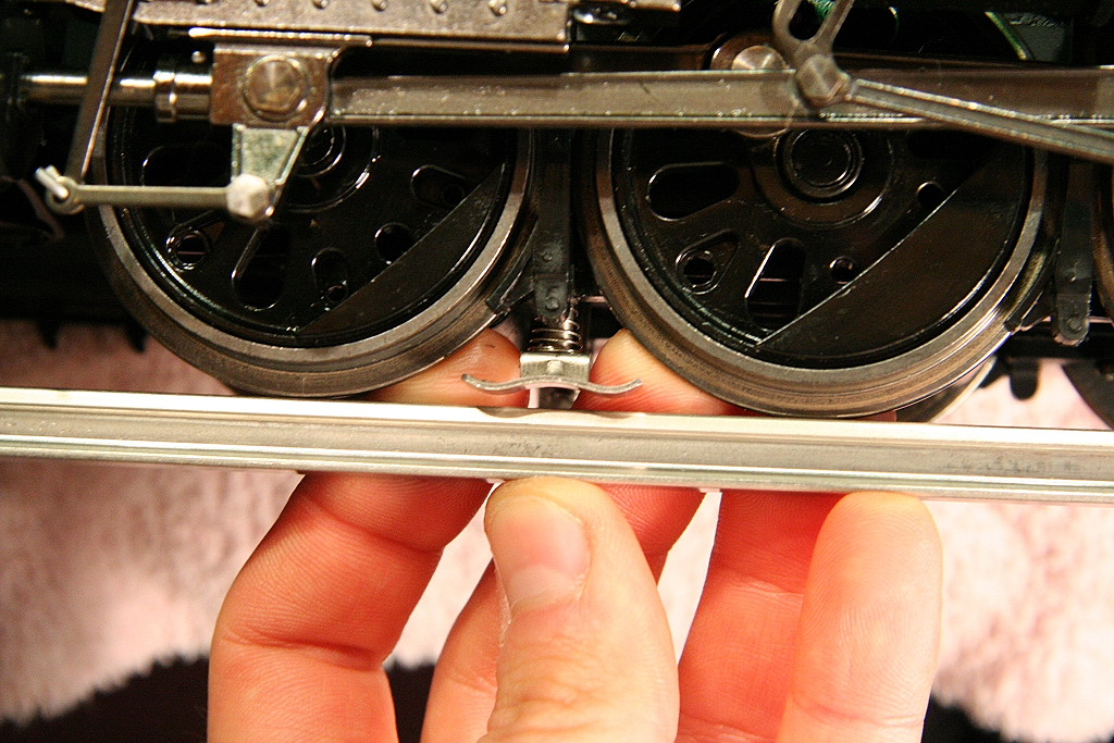
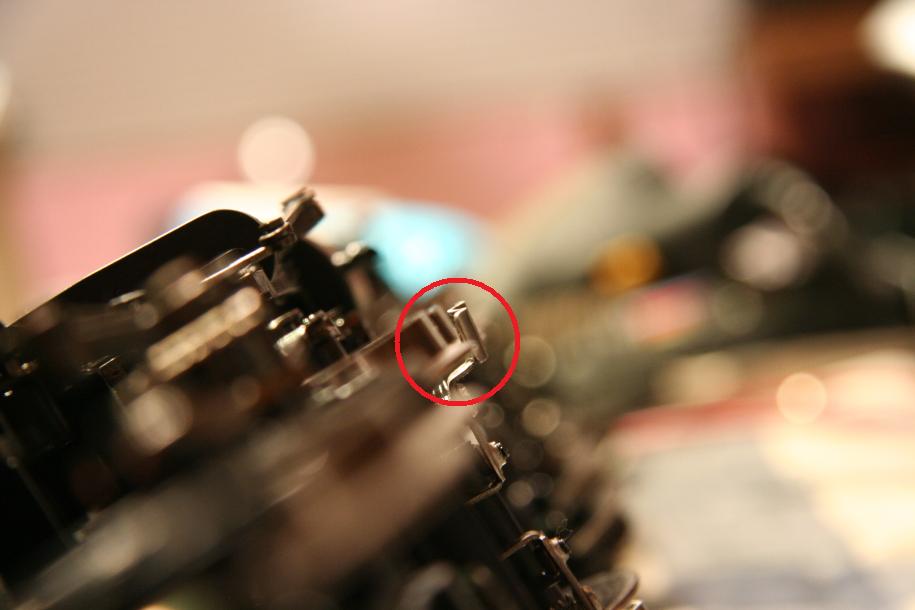
For those having problems with their engine having a slider that dips in the frog which causes the engine get hung up or jerk, you will need to modify the slider just a bit.
In some cases, the slider screw hole was not drilled perfectly straight up and down. This results in the slider being tilted a bit front to back. With the one end of the slider tilted down, that end will have a tendency to drop in the frog as it passes over and get hung up.
The solution I came up with for this was to take and bend the slider pad to compensate and ensure the slider sits level on the track.
I first check to see if the slider is level front to back. (The one in the photo here is already level)
|
||||
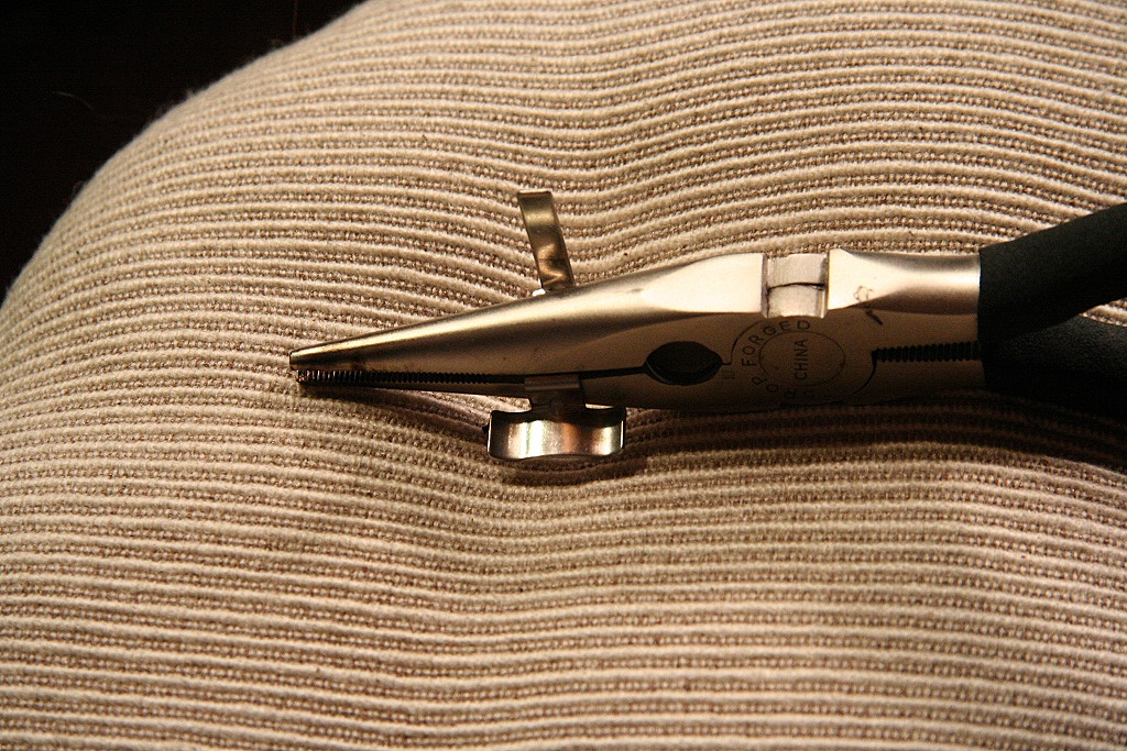
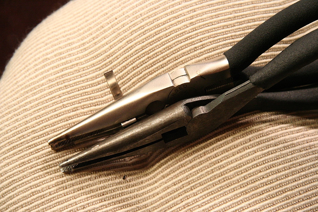
Based on which end is dipped down, I know which way to bend the slider head to compensate.
One way to fix is to take the slider off the engine and then use two pairs of pliers to bend the slider shoe pad so it is oriented correctly against the rail. After you bend, reinstall it and check. You may have to repeat these steps a few times to get it just right. To speed this process you may be able to bend the slider with it on the engine by hand.
|
|
|||
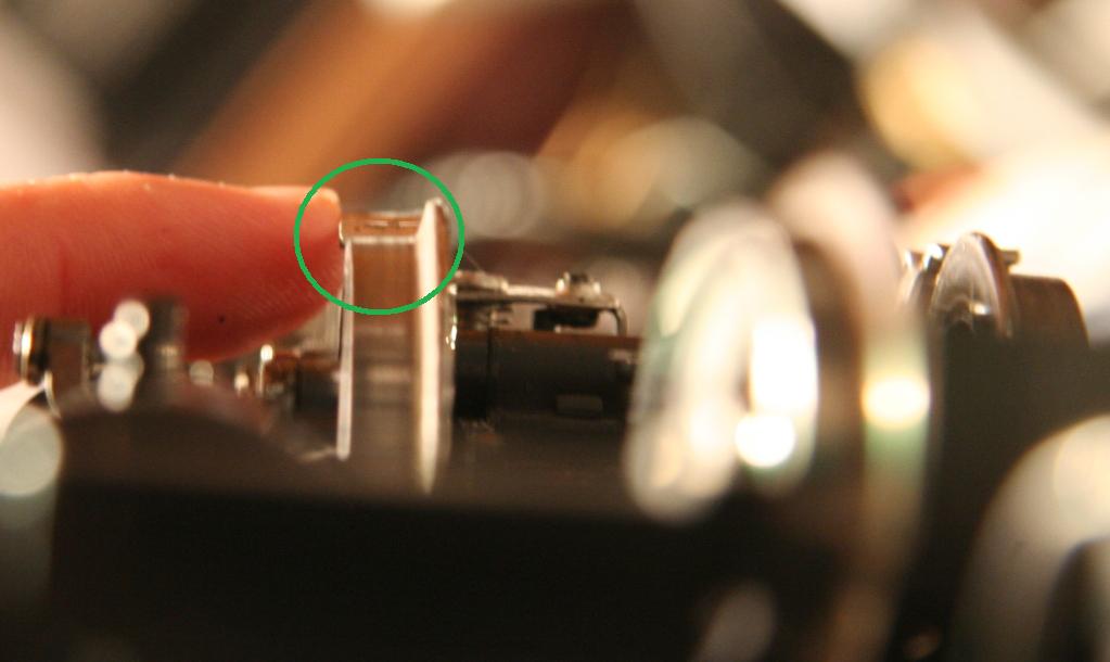
The other thing to check for is to make sure the outside edge of the slider is level as well. If the outside end is dipped too far down it can get caught as well. To tell if it's level, put the engine on it's side and look down the bottom of the drivers and see how the slider looks in comparison. The slider inner to outer level should match.
|
|
|||
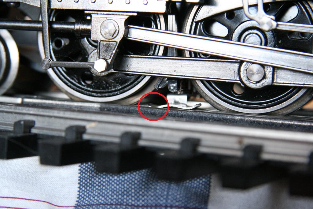
If you still have a slider getting caught in a #6 switch frog, it's probably with the engine entering the main from the siding. (see photos below) If this occurs, you will need to take (likely with a pair of pliers) and bend the end of the slider that's dipping down in frog out just a tad. So in this case below, the left side of the photo is the front of the engine, you need to make the front end of the slider bend out further to the left some. (Assuming the slider is already flat and level from the checks above). Don't bend it too much and remember you are bending it out on the horizontal axis, you want to keep it flat and level. Also, make sure the slider screw is fairly secure in the hole you may need to tighten it down some.
(Note: you may read where some have gone with the method of bending the outside edge of the slider way up to prevent it from getting caught. This is not necessary if you go through these steps noted above. If it's getting caught it's just out of adjustment by likely just a little bit.)
|
|
|||
Once you have your sliders set right they will work reliably from then on, it's just a matter of getting any trouble sliders properly set which really doesn't take too much time.
____________________________________________________________________________________________________________________
08/21/04
Charging the engine's PS2 on-board battery:
See this link: Charging engine PS2 battery (Note: If you have PS3 or upgrade to PS3 this port is no longer need or used as there is no external battery pack to charge)
____________________________________________________________________________________________________________________
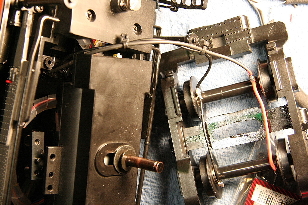
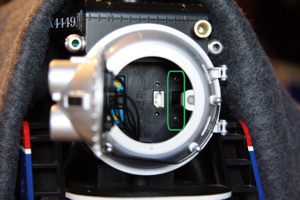
07/21/11
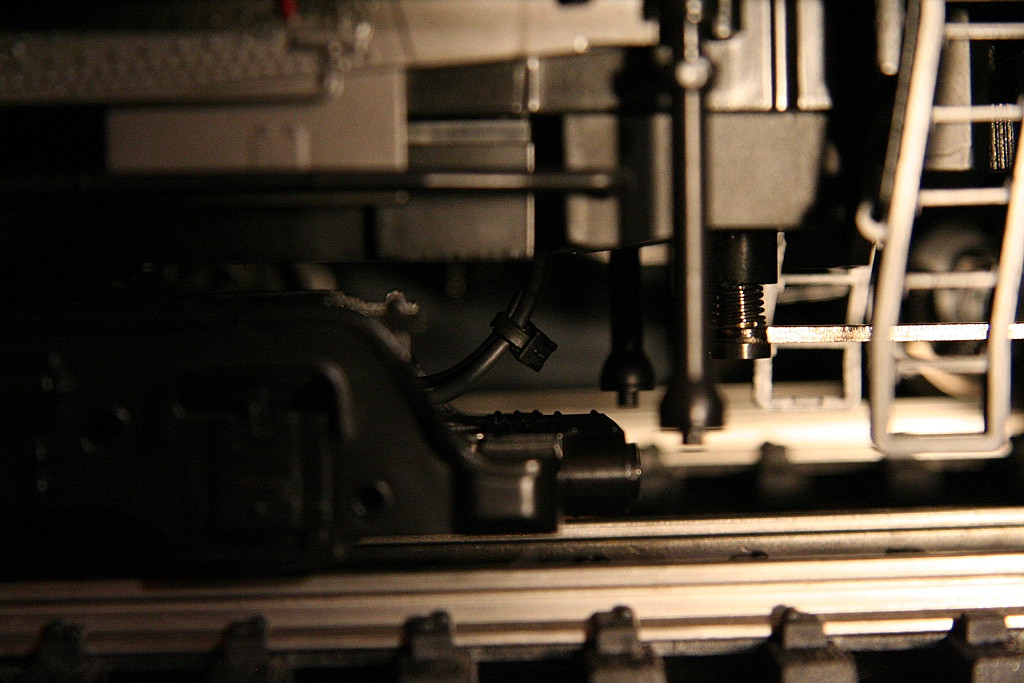
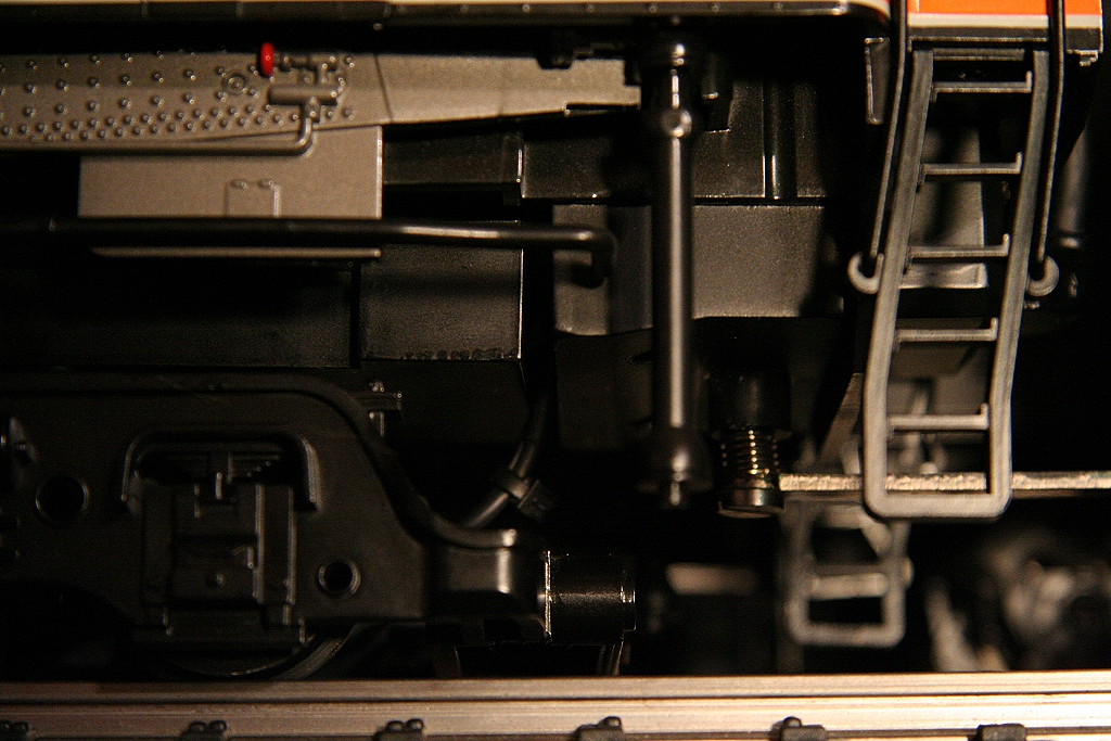
This is the location of the polarity switch on the GS-4. (If your engine has PS3 or was upgraded to PS3 this switch is no longer needed or used as PS3 is not polarity sensitive.)
____________________________________________________________________________________________________________________
11/28/19
Smoking Whistle: Instructions on how to activate:
Do the following steps to activating the smoking whistle:
Note: If your DCS Remote and/or TIU has DCS software version of 3.11 or lower(older), these softkeys below will NOT appear on the remote screen. You must be using DCS v4.00 or higher in order to see the softkeys. Once you update Remote & TIU with updated version, you will need to delete engine from remote and re-add to see the softkeys. If your engine does not come with a smoking whistle, FSW will not be displayed on your remote (SPW may be displayed if engine has playable whistle feature).
Using DCS Remote:
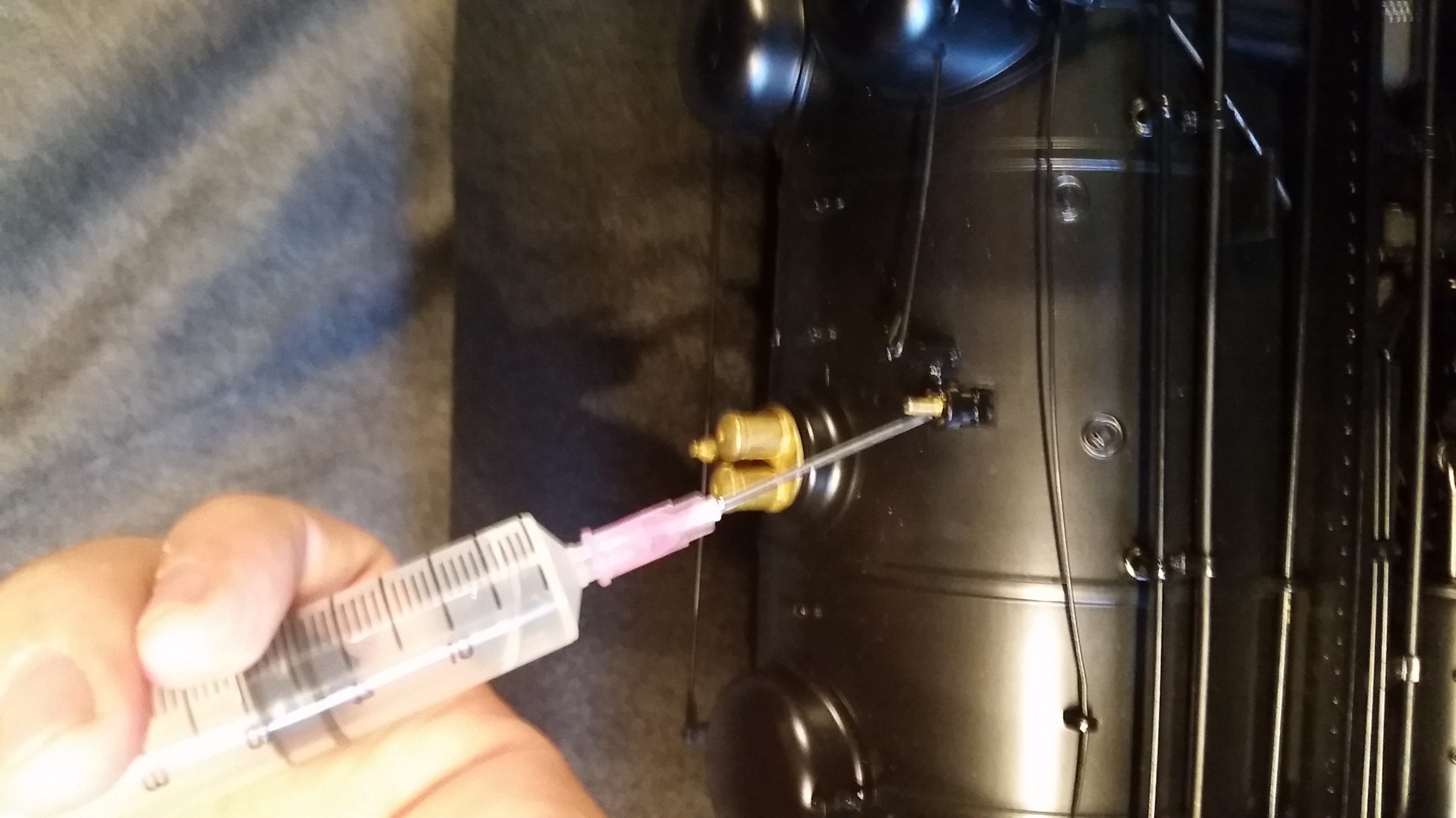
- Step 1: Add 6 drops of smoke fluid into the whistle opening. (If needed)
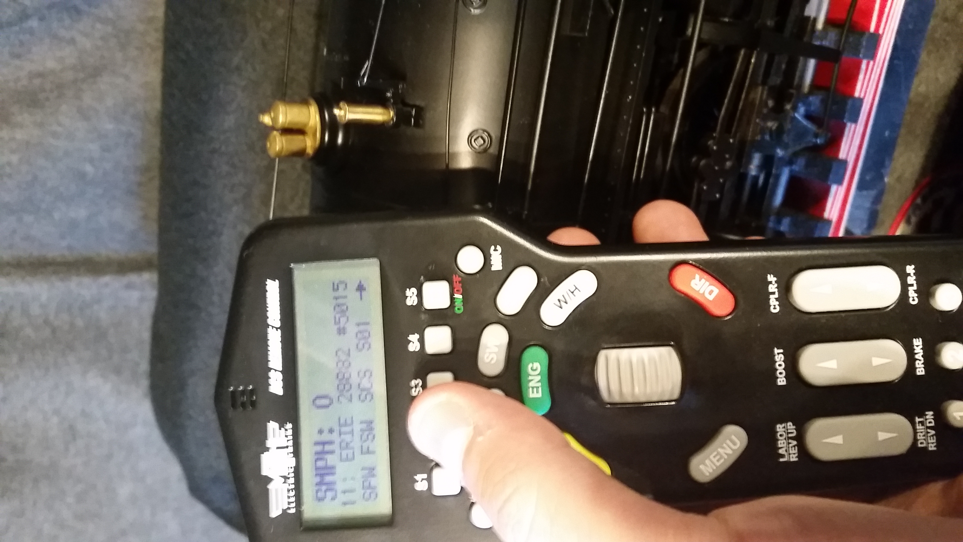
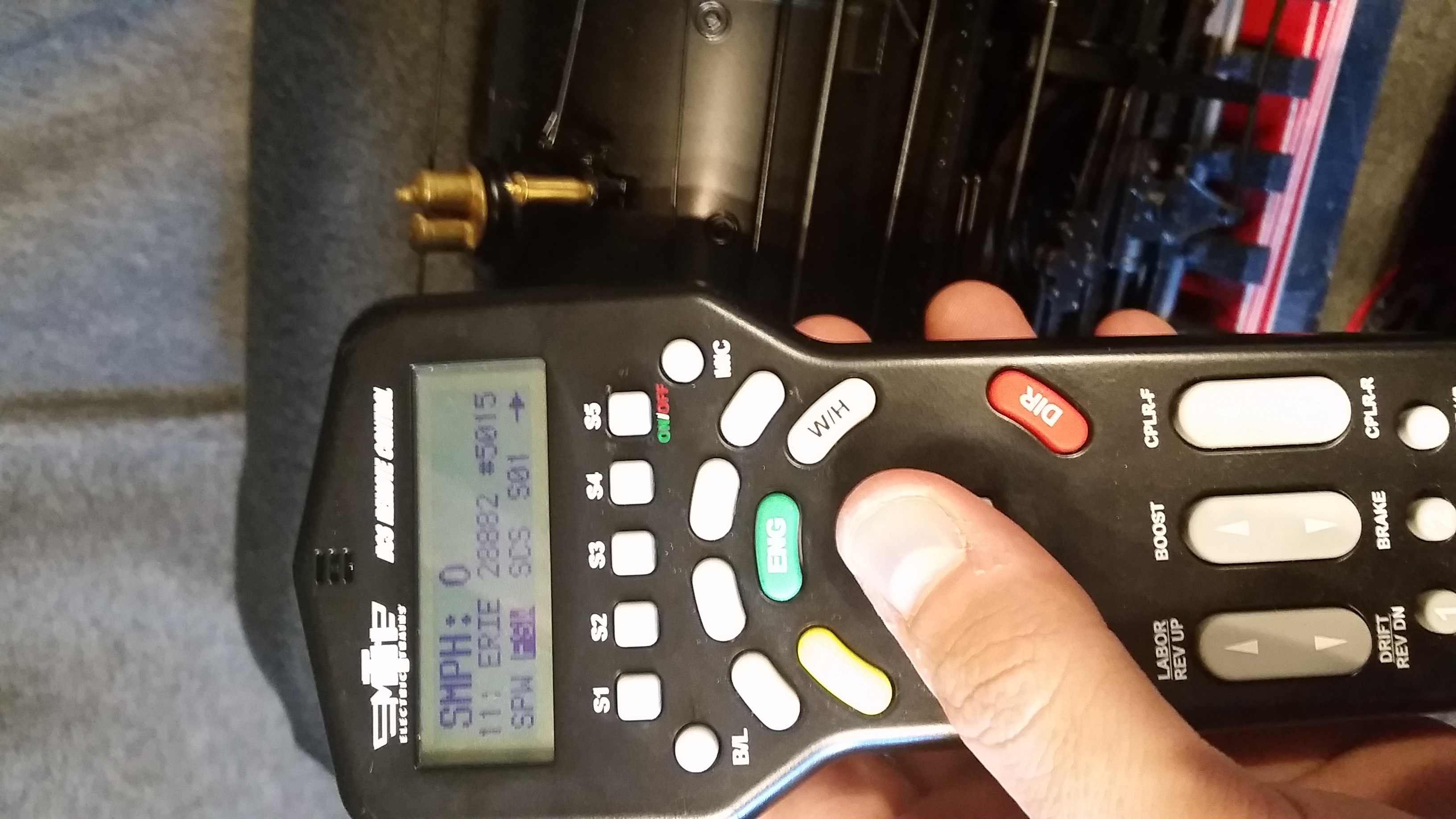
- Step 2a: Press "S2" (FSW) button - (This turns on the smoke whistle heater)
- (Note: You may need to scroll the softkey list with "S5" button to display SPW and FSW labels)
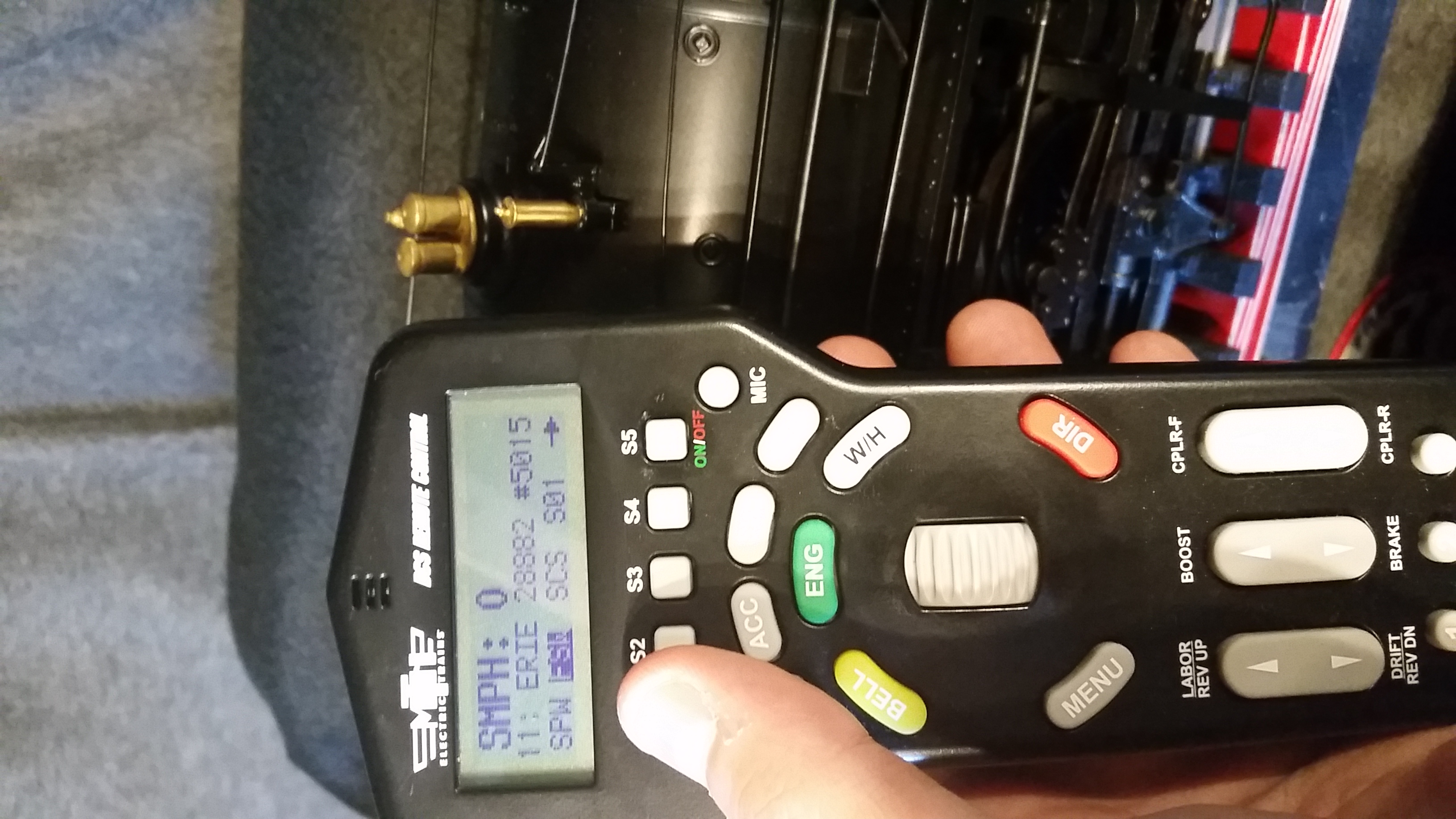
- Step 2b: Turn thumbwheel down - (This updates the screen to confirm FSW is highlighted/activated)
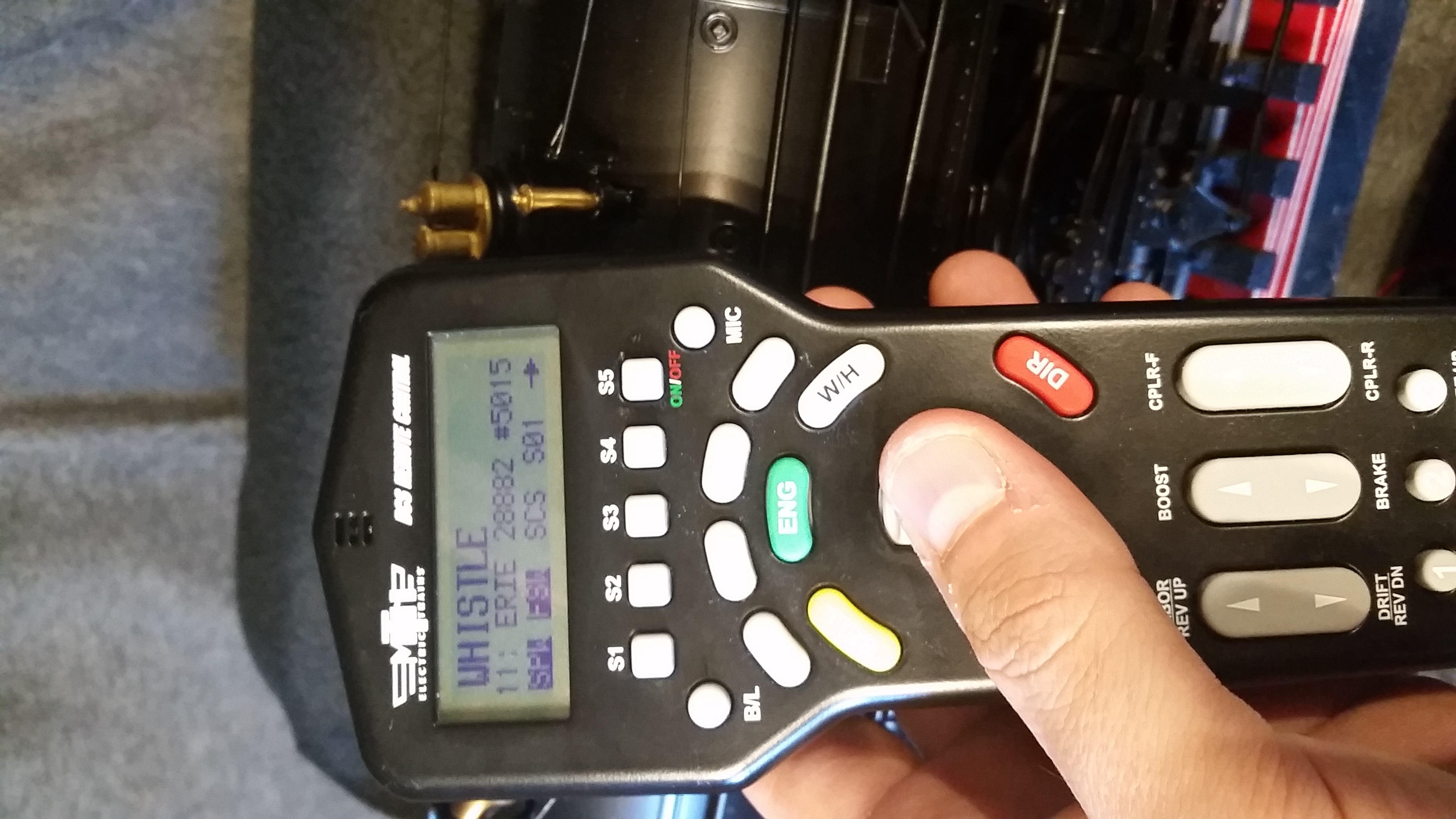
- Step 3a: Press "S1" (SPW) button - (This turns on the Whistle Quill feature)
- Step 3b: Turn thumbwheel down - (This updates the screen to confirm SPW is highlighted/activated)
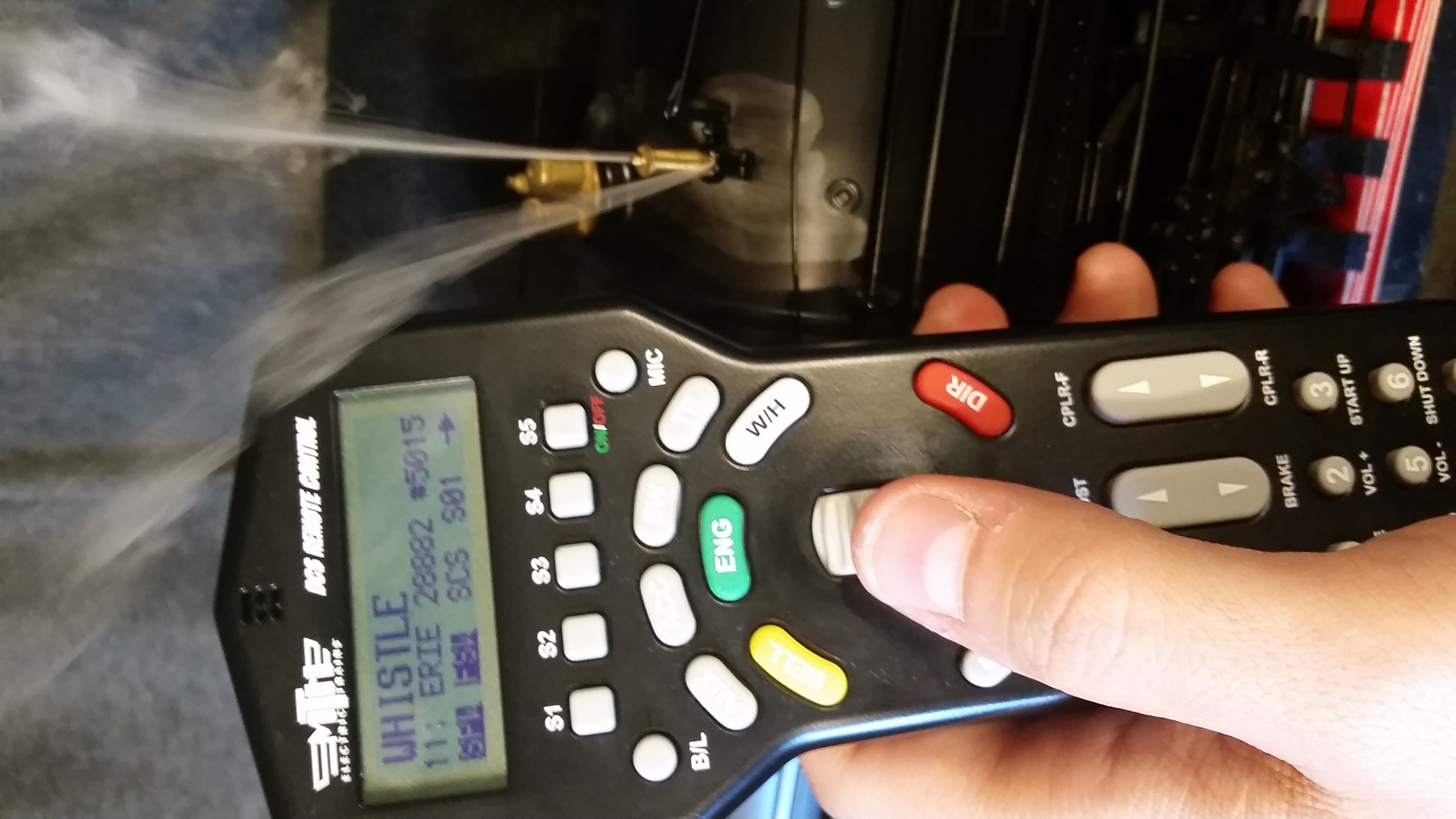
- Step 4: Rotate the thumbwheel up to activate/increase whistle (Three steps of quill are available). Rotate thumbwheel down to deactivate/decrease whistle.
- (Note: If you see smoke coming out the bottom of the boiler and not the top, blow in the top of the whistle hole to clear any fluid bubbles and retry)

Step 1:

Step 2a:

Step 2b:

Step 3a:

Step 3b:

Step 4:
Using WIU w/Wifi and DCS App:
- Step 1: Add 6 drops of smoke fluid into the whistle opening. (If needed)
- Step 2: Go to 3rd screen on DCS App and scroll down and activate "Playable Whistle"
- Step 3: Activate "Whistle Smoke"
- Step 4: Go back to main engine control screen with speed dial and pull on the whistle cord and smoke will come out the whistle.
____________________________________________________________________________________________________________________
Return to the Garden Railroad Modifications page