.gif)
MTH DCS Tips and Operating help
(Operating Protosound 2 or 3 Locomotives and Layout Deployments)
(Updated 8/5/25)
![]()

____________________________________________________________________________________________________________________
General Comments:
This page has been created based on my experiences and personal best practices on deploying layouts running MTH Electric Trains DCS (Digital Command System) and maximizing DCS track communication signal strength. The information on this page is applicable to and has been updated for all scales (G, O gauge, HO, etc) When reading, it is important to note that 'lower track signal' and even 'track signal issues' does not necessarily mean you will have control problems, it just means signal levels will show up as reduced in a track signal check. The intent is to help you focus on the few important key items to save you time in any troubleshooting. Even ignoring most of these suggestions, most will just plug their equipment up and start running without issue.
Two important updates that impact track signal/communication:
1) Rev L TIU with enhanced signal processor (released Mar 2011) - Provides significant signal strength to layout even with PS2 engines.
Example of PS2 engine test on 1600ft oval with PS2 engine: Worlds Longest Train - 2011
2) Protosound 3 boards (PS3 upgrades avail for PS2 engines as of 1/1/16) - Provides a significant improvement in track signal vs PS2 (especially when used with Rev L TIU)
Remember, if you follow the few simple rules for deploying a
reliable track powered layout, then you should have few if any issues with running your
trains under DCS. If you do happen to encounter an issue the solution should be
somewhere on this page. As always you are welcome to email me directly if
you have questions. Email:

Good luck and enjoy.
Raymond
____________________________________________________________________________________________________________________
General information & Considerations:
Overview of the MTH DCS system and all system components:
____________________________________________________________________________________________________________________
Contents:
I. Track/Layout, Power supplies, TIU setup:
II. Engine / Remote / System operation:
III. Tips and Other Information:
IV. AIU items:
V. DCS Software - (How to upgrade your TIU and Remote software):
VII. Modification, repairs and tips on MTH & other mfg engines:
VIII. MTH Parts:
I. Track/Layout, Power supplies, TIU, WIU setup:
- Quick summary checklist: Track/Layout & Power supply: *To maximize track layout communication signal with trains*
- Power Supplies:
Unregulated - *Use Caution*
Pulse Width Modulated (PWM) - *Do not use*
Track/Layout:
Type of feeder wire and connections: Large vs Small stranded, Gauge & Type
Rail joiners: Clamp vs slide joiner - G scale
Brass track vs Stainless Steel - G scale
- Switch control wiring with AIU
Final Step: Tuning your Layout (Deploying Light Bulb/SSLTs to Maximize Track Signal & Communication)
TIU: (Track Interface Unit)
Wire TIU to layout (2 options): Normal vs Passive mode
Protosound 3:
WIU: (Wi-Fi Interface Unit)
Wi-Fi Interface Unit - For control of your Protosound 2 / 3 engines via DCS with your Apple / Android device
Tuning your Layout: (To Maximize Track Signal & Communication)
Passenger or freight cars with lights:
II. Engine / Remote / System operation:
- Quick summary checklist: Operational / DCS System setup:
*Read before you get started to ensure you have good operation*
- 'CHECK TRACK' Error message definition
- 'OUT OF RF RANGE' Error message definition
- ***BASIC STEPS IN TROUBLESHOOTING operational/communication/control issues - Important read***
- Polarity to the TIU / Polarity to the engine(PS2 only) - ('Polarity to engine' applies only to PS2 equipped engines, PS3 is not polarity sensitive)
- Ensure TIU setup is correct in the remote
- 'Out of RF range' errors - (but proper polarity to TIU and engines have been confirmed)
- Which TIU ports to use
- How to provide power to the TIU - (Aux power port vs Fixed 1 ports)
- Wire TIU to layout (2 options): Normal vs Passive mode
- Polarity switch location on engine - (Applies only to PS2 equipped engines, PS3 is not polarity sensitive)
- Problems controlling engine ('Check track' message when giving engine command)
- Engine powers up and starts running when track power is applied, but you have TIU in place and want to use the remote - (Applies to PS2 engines, not PS3)
- Note: This is no longer an issue with PS3
- Loss of all lights and sound on engine while still being able to control it
- Intermittent loss of sound or complete loss of sound from engine
- Intermittent loss of power to engine while running
- Sound cuts-off before shutdown sound sequence is finished when you cut track power
- 'Engine Error' message when trying to add engine - (issue appears isolated to v4.10, v4.20, v4.30 users)
- 'No engine to add' message when trying to add an engine that you know isn't currently added/identified in the remote
- TIU will not power up or no power from a particular Fixed or Variable port
- Ensure the DCS signal is turned to 'ON' for the TIU ports you are using
- Eliminate delays in remote response time and improve engine response/control in areas of bad track signal
- How to perform a factory reset on the engine *Updated for Wifi App*
- If you run an engine equipped with the new Protosound 3.0 (either HO, O or G), you MUST have DCS version 4.20+ installed in your TIU and remote
III. Tips and Other Information:
- USING A QUICK BLOW FUSE - VERY IMPORTANT!!!!
- Improving the operating range of the wireless handheld DCS remote to 300+ ft
- Track polarity: How to tell you have the correct polarity going to the engine - ('Polarity to engine' applies only to PS2 equipped engines, PS3 is not polarity sensitive)
- How to add an engine to the layout when other engines are already powered and running
- Track voltage levels and it's effects on DCS operation
- Upgrading your TIU and Remote software
- Volt and Ammeters - How to install and where to buy
- Remote control for Power supply power cut-off - (great for emergencies)
- Charging the engine's PS2 on-board battery - (Only applies to PS2 equipped engines, PS3 no longer has this.)
- Triggering the Bell and Whistle when running your engines under variable throttle power only
V. DCS Software - (How to upgrade your TIU and Remote software):
- DCS (for Remote & TIU) - (Firmware for TIU and Remote) *Click here for photo of DCS TIU and Remote*
Current Versions:
<---- LATEST VERSION
DCS v6.00 - (Latest version - NOTE: You MUST use the new DCS Loader version 5.00 to load to TIU&Remote) (Upgrade the TIU first.)
DCS Loader program - (PC Software for computer to upload firmware to TIU/Remote or upload/download sound files to engines)
Current Version: (v5.00 - New version required to load DCS version 5.00 to TIU and Remote)
(WARNING: You MUST use DCS Loader 2.20+ for Protosound 3.0 engines. Using older version will disable an engine's PS3.0 electronics.
Uninstall all prior 2.xx versions of the DCS loader before installing updated version)
DCS Loader Program v5.00 (1.2mb) - (Latest version)
Windows 7/8 USB Drivers if using TIU via USB port - Use only if needed
Old/Outdated versions: (*Click to access old/outdated prior versions including v2.30 (32bit) *)
- DCS Commander Software - (Use DCS Loader program v2.20 or greater) *Click here for photo of DCS Commander*
INSTRUCTIONS: How to upgrade your TIU and Remote software
VI. DCS Users Manual: (Download full DCS User Manual: MTH DCS Users Manual (Fifth Edition))
VII. Modification, repairs and tips on MTH & other mfg engines:
VIII. MTH Parts:
For MTH Parts please email me at:
Mike's Train House MTH DCS Protosound 2 Protosound 3
____________________________________________________________________________________________________________________
I. Track/Layout, Power supplies, TIU Setup:
Quick summary checklist: Track/Layout & Power supply: *To maximize track layout communication signal with trains*
Track/Layout & Power supplies:
- Follow guidelines for wiring your layout for your given layout conditions. (see How to wire your layout)
- Use a good quality throttle type DC (or AC) power supply. (Please read Power supplies for important additional info)
- Use a new Rev L (or newer) TIU
- Ensure good track joint connections
- One Gauge/G scale: Use direct-to-rail rail-clamps as opposed to slider rail joiners for all connections (Rail clamp/joiner types)
- In O gauge, sand the top of the center rail down to remove the black coating (as some cause high resistance and poor power transfer to the power pickups)
- If outdoors with G scale, use connectors that won't corrode for feeder wire connections to the track. (thoroughly solder the connector to the end of the feeder wire ends)
- Use preferred feeder wire (preferred with finely stranded wire, not solid core) (If outdoors use wire with thick rubber insulation for outdoors, see Wiring for more info)
- Use jumper wires across switches to maintain power continuity at the track level.
- O gauge (3 rail): Jumper center rail. (I recommend adding jumpers to outer rails cut at the frog)
- 2 rail (O gauge, G scale, HO, all): Jumper for rails cut by switch frog.
- Use feeder wires:
- G scale:
- 100ft+ ovals with Stainless Steel track
- Consider using a centralized power feeder distribution point (star wiring configuration) on layout ovals over 500ft-1000ft+
- O gauge:
- Consider using a centralized power feeder distribution point (star wiring configuration) on ovals over 200ft+
TIU output ports: If using more than one TIU port on layout, the wires/tracks that they are connected to must be electrically isolated from each other.
Utilize incandescent light (or new SSLT - Solid State Layout Tuner)
Use on each of the TIU output ports being used if older non-Rev L TIU (see Tuning your layout with Light Bulbs/SSLTs)
On larger ovals 150+ deploy 4 around the layout at the track level equally spaced out.
For layouts with really large ovals where you still see signal levels you want to improve use the method noted here: How to Deploy Light/SSLT
Mike's Train House MTH DCS Protosound 2 Protosound 3
____________________________________________________________________________________________________________________
Type of Power Supply: (AC vs DC / Linear vs Switching Mode / Throttle vs Regulated / Unregulated)
This section on power supplies speaks to running your MTH PS2/PS3 engines under DCS Digital Command Control using your TIU (Track Interface Unit).
Before reading further, to provide the short summary, the absolute best power supplies to use for DCS will be:
- AC power: MTH Z4000 or AC power brick
- DC power: Bridgewerks Throttle type
(Note: In terms of absolute performance, there is no difference between the AC and DC power supplies noted above)
The type of power supply you select can have a significant impact on the resulting DCS signal strength and operational problems when running your MTH trains under DCS control using your TIU. It is likely that there are more power supplies that deliver solid track signal and good to use with your DCS engines than are listed on the MTH approved list, but it is important to understand not all will give the same level of performance. There is a wide range in performance with regards to resulting overall DCS signal on the track depending on what type of the power supply you use and the number of feet of track you have on your layout. For most users the vast majority of power supplies will work sufficiently, but as the size of your layout grows with more feet of track along with the number of amps output the weaknesses of some cheaper power supplies can start to show. If you have 120ft of track total then just about anything will do, if you have a 1000ft, then the power supply you choose becomes more critical. The bottom line is, this is the one area that trying to save a little bit of money by purchasing an inexpensive power supply can lead to more headaches than it's worth. As they say, you get what you pay for.. and that holds true here as well.
When selecting a power supply you will have two types of power to choose from, AC or DC.
(PS2 & 3 O Gauge and G scale/One gauge engines can run on either AC or DC power. PS3 HO Scale is DC ONLY with, PS3+ for HO 3 rail uses AC or DC power)
AC power:
If you're running O gauge in most cases you will want to use an AC power supply as historically that is what all O gauge manufacturer engines use. You will basically have three options: (You can run your One Gauge or G scale engines on AC power as well)
High-end/quality throttle AC power (Example: MTH Z-4000 (MTH #40-4000)
Power brick/block AC power with connector (Example: MTH 40-1000A)
Low cost throttle AC power (Example: Z-1000 throttle power supply (40-1000))
Of the options above, 1 & 2 are the only ones you should use when running under DCS Digital control (with TIU and Remote/WIU) and will provide the same levels of track signal quality.
Option 3 should never be used with the throttle to provide track power for DCS Digital control. (In this case you must remove the throttle and plug the power brick directly into the TIU input ports (Fixed 1, Fixed 2, Var1, Var 2) otherwise you will greatly degrade the DCS signal communication on the layout.
- Recommended Voltages: 0-24v (O Gauge / One Gauge) (under DCS Command Control with TIU and Remote use 18-24v)
DC power:
If you're running G scale/One Gauge (or HO Scale) you will want to use a DC power supply as that is what most/all of manufacturer engines use for these scales. For DC power hands-down I prefer the Bridgewerks line of power supplies over all other DC power supplies because: 1) They provide the best track signal results 2) The Bridgewerks throttle type power supplies are able to provide 24v+ to the track (all others on the market only output 18v under a load) 3) Are made in high amp versions for the big power needs in G scale and 4) Are well made/high quality.
Recommended DC power supplies:
Best:
- Bridgewerks (Throttle type power supply) *Use 'To Track' output terminals for best results*
- https://bridgewerks.com/product/magnum-sr-series/ (5, 10, 15 amp)
- https://bridgewerks.com/product/magnum-20srs/ (20 amp)
- Bridgewerks: TDR25 (25 amp) (These are no longer made)
- Bridgewerks (Power Mag regulated power supply)
- https://bridgewerks.com/products/ (25 amp @ 24volts) (see Power Mag)
Good:
- USA Trains Power 10 (If using w/TIU set Momentum=OFF. Also set to "G")
- **PLEASE SEE THE CAUTION/NOTE BELOW ON RECENT ISSUES WITH THE USA TRAINS 10 POWER SUPPLY**
- MRC Power 'G': http://www.modelrec.com/
- Bridgewerks Mag 15 (new model regulated at 24v output) (This may not provide the same track signal levels as their throttle type supplies)
Believe safe to use:
- Aristocraft 5460 (10amp) - (Looks like Automotive Battery Charger)
Not Recommended:
- Switching mode power supplies: (These can be used but I would avoid them)
- AC Outputs on Bridgewerks power supplies: (Will get lower track signal levels)
- Bridgewerks fixed output terminals on Throttle type power supplies. *Use 'To Track' output terminals for best results*
Avoid/Do not use:
- Pulse Width Modulated (PWM) power supplies
- DO NOT USE PWM power supplies!
- PWM will Damage your MTH TIU and possibly PS2/PS3 engine electronics.
- Will also cause severe control/operational issues because of the PWM/PWC power.
- Note: If you are unsure if your power supply is PWM, contact the Manufacturer to confirm if it is Linear or PWM/PWC.
- Aristocraft:
- Revolution Base Station (added between your power supply and TIU/layout that allows control/regulation of track voltage):
- Model #57005S / 57004S is PWM/PWC output (Do not use!)
- Model #57007S / 57006S indicates it is Linear (not PWM) and would be safe to use
- CRE-55400/ART5400 (is PWC power)
- CRE-55460 Everest 15amp (is PWC power)
- CRE-55468 Everest 15amp (is PWC power)
- MRC Throttle Pack 9950 or 9900 (These are PWM power supplies, Do Not Use!)
- Bridgewerks Mag 15 (old version with unregulated output of 35+ volts)
- Caution:
- Aristocraft Train Engineer (At least some are PWM/PWC) (if it has a Linear/PWC switch, do not use on PWC setting. Linear would be ok)
If you aren't sure if your Train Engineer is PWM/PWC or Linear, then I would assume it is PWM and not use it until you confirm for sure.
Caution/Notes:
- USA Trains Power 10:
Testing shows this power supply has excellent track signal results and is one I normally recommend under the Good to Use list. However as of 3/27/19, I have encountered 3 separate customers within a few week period where engines stop running with their lights flashing/pulsing (PS2 or PS3-One gauge steam) . Engine won't move with speed dialed in and engine makes noises when on the track. It appears USA has a bad batch of power supplies where they have an intermittent problem where they pulse track voltage on/off to the track rapidly. If you see this STOP USING THE POWER SUPPLY IMMEDIATELY! (Note that if you have PS3 with LED lights then lights wont flicker/pulse but will malfunction/not move.)
Voltages:
- O gauge/One Gauge: 0-24v recommended voltage (under DCS Command Control with TIU and remote use 18-24v)
- HO Scale: 0-24v recommended voltage (under DCS Command Control with TIU and remote use 18-24v Maximum)
- Note: For HO, I recommend a maximum of 18v DC.
DC Power supplies: (Additional information on different types)
Linear (non-switching mode) Power supplies - (DC power supplies)
Using a Linear power supply will generally give you the cleanest power output which will result in the best overall track signal levels as it provides an unmodified waveform output. (Note: Linear power supplies can be identified (aside from labels saying it is) by it's weight and are much heavier than the standard switching mode type because of the large copper wound transformer inside.) It is important to note however that not all linear power supplies are created equal, and just because the power supply uses a large copper wound transformer doesn't mean you will get the same performance as the top performing Bridgewerks. Based on my experience, the Bridgewerks line of power supplies provide the most solid track signal levels when compared to the others. ('Solid' means you will get higher signal levels to more linear feet of track at higher amperage levels with fewer problem areas.) The key is their use of linear regulators that provide the actual voltage output and are between the transformer output and the output actually provided to the track. If your transformer uses these types of linear regulators then I would expect you would get similar performance as a Bridgewerks, but the BW are the only model train power supplies I've ever seen that use them. Example of linear regulator: Linear Regulator
Switching Mode Power supplies - (DC power supplies)
These will be characterized by being relatively low cost and very light weight. These are what most G scale train manufacturers sell and what most people try to buy or already have. You will get decent track signal levels but as the number of feet you attempt to provide signal to increases, so will your issues with track signal. You will also likely have increasing track signal problems as the total overall amperage levels increase. This is all due to the increasing amount of 'hash' the switching power supply is outputting coupled with the fact the DC wave form isn't really pure. It is for these reasons I strongly recommend a Linear (non-switching mode) power supply. However if you already have one of these power supplies, try it and see how it works for your situation.
Examples of Switching Mode Power Supplies:
I've found no distinct difference in resulting signal quality between my throttle type supplies such as the Bridgewerks Magnum SR 15amp ( http://www.bridgewerks.com/Pages/MagnumSRSeries.html ) and the regulated Bridgewerks Power Mag ( http://www.bridgewerks.com/Pages/PowerSupplies.html ) I have not tested the Bridgewerks Mag 15 (which is a DC power brick)
If you have an unregulated power supply, it will be safe to use as long as the max voltage output is 24v. If you have one of these power supplies and are not sure, verify the voltage output with a voltmeter. Never assume any power supply is putting out voltage at safe levels!
- Bridgewerks Mag 15: (Older version) One particular WARNING: DO NOT USE the older style Bridgewerks Mag 15 by themselves to power the track. (Click for Photo: Pic1, Pic2) The Mag 15 (not to be confused with the Magnum S-15 or regulated Power Mag) is an unregulated & non-throttle type power supply and can output 35+ Volts DC EVEN UNDER A LIGHT LOAD! DO NOT use these by themselves to power the track to run an engine under DCS under any circumstances, regardless what you are told. There is no way to regulate or adjust the output power on the Mag 15 itself. I understand these power supplies were made with the intention of powering the Bridgewerks line of unpowered throttles. If the Mag 15 is used with an unpowered throttle it will be safe to use as you can limit/adjust the voltage to the track with the throttle.
- UPDATE 04/4/15 on the Mag 15: Bridgewerks has produced an updated "Mag 15 -R" that outputs a consistent 20v regardless of load. (Can also order a custom voltage output of 18v through Bridgewerks) If you have purchased a new unit and are not sure, check the voltage with a voltmeter and read 30v or higher do not use. If wanting to use with MTH DCS Protosound 2 / 3 layouts, use this only with a Bridgewerks unpowered throttle for best signal strength. Even with the updated voltage I do not recommend using these as stand-alone power supplies. Purchase a Bridgewerks throttle type power supply.
Pulse Width Modulated (PWM): (*Do not use*)
Do not use these types of power supplies with your Protosound 2/3 equipped engines or DCS set (TIU & Remote). MTH specifically advises that users not use this type of power supply in the user manuals supplied with the engines they sell.
Note: This includes the Aristocraft Revolution Base Station. Do not use Revo Base Station between your DC power supply and the TIU/Layout. It WILL damage your TIU and possibly PS2/PS3 engine electronics.
Note: If you use AC power it will allow you to use and vary the track voltage outputs on the 2 TIU Variable ports (Var 1 and Var 2) with the handheld remote
Note: Protosound 2 equipped engines are not designed to work powered from a DCC booster/power source. The new Protosound 3 boards in O and G are capable of running in a DCC environment.
Mike's Train House MTH DCS Protosound 2 Protosound 3
____________________________________________________________________________________________________________________
Track/Layout:
The following is the basic set guidelines for deploying layouts in all scales (O Gauge, G, HO, etc) that allows for simple, repeatable results.
Key Guidelines:
Have continuous electrical continuity at the track level for all rails, do not add insulators on any rails to break an individual oval into isolated blocks.
Do this for all layout oval sizes and model train gauges (O gauge, G scale, HO scale, etc)
Ensure you have reliable connections at all rail joints.
For large ovals (100-200ft+), run each oval on a dedicated TIU channel (Fixed 1, Fixed 2, etc) and keep those ovals electrically isolated from each other.
Use a Buss / Daisy chain feeder wire configuration for ovals over 100ft+
- G scale:
- 100ft+ ovals with Stainless Steel track
Consider adding a centralized power feeder distribution point (star wiring configuration) for: (If Buss/Daisy chain feeder setup already in place, add star setup to existing buss wiring)
- G scale:
Layout ovals over 500ft-1000ft+
O gauge:
Layout ovals over 100-200ft+
HO Scale:
Layout ovals over 100ft+
Add jumper wires for all rails that have their electrical continuity cut at switches.
O gauge 3 rail: Jumper center rail (I also jumper outer rails cut by frog)
2 Rail (O gauge, G, HO): Jumper all rails cut by switch frog
TIU: Mount the TIU horizontally (Flat) and position it 12+inches higher the layout itself (This can improve overall layout signal strength)
TIU output ports: If using more than one TIU port on layout, the wires/tracks that they are connected to must be electrically isolated from each other.
Utilize incandescent light (or new SSLT - Solid State Layout Tuner)
Use on each of the TIU output ports being used if older non-Rev L TIU (see Tuning your layout with Light Bulbs/SSLTs)
On larger ovals 150+ deploy 4 around the layout at the track level equally spaced out. (This covers most layouts)
For layouts with really large ovals where you still see signal levels you want to improve use the method noted here: How to Deploy Light/SSLT
Block / Feeder wire configuration: (UPDATED 09/08/16)
As noted in the How to wire your layout section above, I recommend keeping each oval as one continuous electrical loop at the track level with no insulators on any rails. (Regardless whether O gauge, G, HO etc) As ovals get big enough you may want to add a feeder wire setup to provide power/signal redundancy.
Buss/Daisy chain: w/continuous electrical oval/block (no insulators used on any rails on entire oval)
Summary: One connection to the oval from Power supply / TIU.
Pros: Solid signaling, Simple, Minimizes amount of jumper/feeder wire used
Cons: For large ovals 500-1000ft+ will benefit from adding Centralized Power Distribution Point aka "Star wiring" (see below)
Centralized Power Distribution Point: (aka: "Star wiring" Traditionally used in O Gauge)
Summary: Power supply/TIU runs to single distribution point and from there makes connection to multiple points on the oval
Pros: Allows for solid signaling for the largest layouts
Cons: May use more linear feed of feeder wire
Straight line (linear) *Not Recommended*
Pros: Simple, only one light/SSLT at one termination point per loop
Cons: May encounter issues with multi engine consists on large ovals (235ft+) and offers less power feeder redundancy
Buss/Dasy Chain: (w/continuous electrical oval/block, no insulators used on any rails on entire oval)
When wanting to add feeder wires on a layout, this is the first configuration I recommend. (for O gauge, G, HO etc) With this configuration you take the output from the TIU and run one wire pair to a single point on the track and keep the oval itself as one continuous electrical block with no insulator clamps (can use use additional feeder wires or not). This setup minimizes the amount of wire used and allows for more drops for less wire. (For G scale outside, if you want to add feeders, I recommend using daisy-chained vs buss.) Even if you decide to add a centralized power distribution point (Star wiring) setup later, always start with a Buss/Daisy Chain setup as the foundation first. For G scale I recommend power connections to the track every 24ft. For O gauge/HO every 10ft.
If you have ovals that meet the below conditions you will want to consider adding a centralized power feeder distribution point (star wiring configuration) in addition to the Buss/Daisy Chain.
G scale:
- Layout ovals over 500ft-1000ft+
O gauge:
- Layout ovals over 200ft+
HO Scale:
- Layout ovals over 100ft+
It is important to note again, make sure you add jumper wires at all switches/turnouts across all rails that have electrical continuity cut. For O gauge, add a jumper wire on each side for center rail and outer rail as needed. For 2 rail (O gauge, G scale, HO), add jumper for the rails cut by the frog.
Lastly I recommend utilizing incandescent lights (or new SSLT - Solid State Layout Tuner) deployed around the oval to maximize overall signal levels
- Use on each of the TIU output ports being used if older non-Rev L TIU (see Tuning your layout with Light Bulbs/SSLTs) (not needed for Rev L TIU)
- On larger ovals 150+ deploy 4 around the layout at the track level equally spaced out. (This covers most layouts)
- For layouts with really large ovals where you still see signal levels you want to improve use the method noted here: How to Deploy Light/SSLT
Example: (Daisy Chain)
Centralized Power Distribution Point ('Star Wiring'): (w/continuous electrical oval/block, no insulators used on any rails on entire oval)
I recommend adding this wiring setup if you have ovals that meet the below conditions (in addition having Buss/Daisy Chain).
G scale:
- Layout ovals over 500ft-1000ft+
O gauge:
- Layout ovals over 200ft+
HO Scale:
- Layout ovals over 100ft+
As noted in the Buss/Daisy Chain section above, I always recommend starting with the Buss/Daisy Chain first, then add this star wiring as needed. If you already have a Buss/Daisy Chain feeder setup in place, make your connections from the star wiring to the same point where the Buss/Daisy Chain connects to the track. Note that you of course can just use the star wiring without the buss/daisy chain in-place with no problem which is what most in the past have done.
The Central Distribution point doesn't necessarily need to be physically located in the middle of the layout and the feeder runs don't have to all be equal-distance. The purpose as per my recommendation is to provide a short cut path from the power supply feed to some of the farthest distance points on the layout. This can improve overall signal on large ovals.
It is important to note again, make sure you add jumper wires at all switches/turnouts across all rails that have electrical continuity cut. For O gauge, add a jumper wire on each side for center rail and outer rail as needed. For 2 rail (O gauge, G scale, HO), add jumper for the rails cut by the frog.
Lastly as before I recommend utilizing incandescent lights (or new SSLT - Solid State Layout Tuner) deployed around the oval to maximize overall signal levels
- Use on each of the TIU output ports being used if older non-Rev L TIU (see Tuning your layout with Light Bulbs/SSLTs) (not needed for Rev L TIU)
- On larger ovals 150+ deploy 4 around the layout at the track level equally spaced out. (This covers most layouts)
- For layouts with really large ovals where you still see signal levels you want to improve use the method noted here: How to Deploy Light/SSLT
Example: (Centralized Power Distribution Point ('Star wiring') w/Daisy Chain feeder wires)
Straight line (linear) configuration: *Not recommended*
**This configuration is listed only to cover it and provide information.**
In this method you select a track joint closest to where you want to connect your TIU/power supply feeder wire and add an insulator clamp to both rails at that point. On one side of the insulator clamp attach your TIU/power supply wire (preferably to a dedicated all metal clamp) and on the other side (the end of the electrical block) add one light or an SSLT. (For more info on light/SSRBDs see: Lights/SSLTs(Solid State Layout Tuner))
Because of some issues I've encountered and the reduced power reliability of having the power feed at only one end, I do not recommend it being used. (Adding daisy chained power feeders reduces this reliability issue but I still do not recommend using this method)
Example: (without additional feeder wires)
Click picture to enlarge
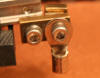
Photos of track power wire connection points (G scale):
Daisy Chain Feeder jumper connection points (One is end point the other is start point)
The feeder jumper connection point above photo includes:
One set of jumper wires going ~24ft to the left - (1 pair)
One set of jumper wires going ~24ft to the right - (1 pair)
Mike's Train House MTH DCS Protosound 2 Protosound 3
____________________________________________________________________________________________________________________
Type of feeder wire and connections: Large vs. Small stranded, Gauge & Type:
For low voltage applications such as model trains it is generally recommended (but not required) to use finely stranded wire.
Recommended wire:
- O gauge: 18awg (finely stranded)
- G scale: 12 to 14awg (Outdoor low voltage landscape wire with thick rubber insulation) (Example from local Home Depot/Lowes)
Connection to track:
- O gauge: Recommend direct soldering of the feeder wires to the rail.
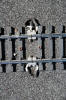
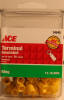
- G scale: Recommend using ring terminals that won't heavily corrode or oxidize such as shown below. Solder wire to ring terminal then attach the ring to a Split Jaw clamp to the rail.

Example of feeder wire connection points on layout.
Mike's Train House MTH DCS Protosound 2 Protosound 3
____________________________________________________________________________________________________________________
Type of rail joiners: Clamp vs Slide joiner (Mainly applicable to G scale)
This is an area more about having a reliable track powered layout as opposed to reliable track signal. Poor track connections can lead to reduced levels of track signal but this will only happen in cases when you have connections that start to become barely able to pass electrical current. The bottom line rule here is, if you have a reliable and solid foundation for a track powered layout, then you will have a solid foundation for running MTH DCS w/Protosound. If you run with only slide-joiners, over time you will run into electrical conductivity issues at those joints and that can possibly lead to DCS signal issues. When this happens your primary problem will be from the engine not getting proper electrical current to run, but it may also show up as reduced levels of track signal. I learned early on that Split-jaw direct-to-rail clamps are really the best way to go in order to have a reliable and maintenance-free track powered layout (indoors and out). While they do increase the cost of deploying the layout you really save yourself headaches in the long run.
I personally ran a 120ft loop of all Stainless Steel track with SS slider joiners for two years and never had signal issues, even when I started encountering electrical conductivity problems with some joiners. (Example: joiners getting hot from trying to pass current when the joiner connection was not snug and dirty.) So the DCS signaling isn't that sensitive, but to save yourself trouble in the long term, I recommend rail clamps.
See this page for more info: Rail clamp/joiner types
____________________________________________________________________________________________________________________
Maximum number of linear feet of track to provide track signal to per TIU port
The maximum number of feet you are able to successfully provide solid track signal to will depend on a few factors.
Greatest impact:
How layout is wired (Click here for more information: How to wire your layout)
Solid connections at all rail joints:
G scale: Use Direct to Rail Clamps - (Click here for more info: Rail clamp/joiner types )
O gauge & others: If you have bad/questionable joints, solder them or add jumper wires.
TIU: Use Rev L or newer TIU for best track signal results
PS3 vs PS2: (Protosound 3 boards have much stronger signal strength vs PS2)
Power supply - (Click here for more info: Type of Power supply )
TIU Location: Locate TIU in a position above the layout (about 12 inches or more) and mount horizontally. (This can increase track signal levels on the layout)
Lesser impact:
Track type: Brass vs Stainless steel (G scale)
See Brass and Stainless Steel rail for more information
Comment: I was able to successfully deploy a 1600ft oval for the World's Longest Train attempt in 2011 with a single TIU (Rev L) using PS2 engines, DC and the best practices as noted. (Worlds Longest Train - 2011)
Mike's Train House MTH DCS Protosound 2 Protosound 3
____________________________________________________________________________________________________________________
Brass track vs. Stainless Steel: (Mainly applicable for G scale)
This is one area that will impact how you deploy your layout regardless of the control system you plan to use. Compared to Brass track, Stainless Steel rail has a much higher electrical resistance which means that as you try to pass an electrical current through it, you will see a greater drop in the voltage at points: 1) the further away from the nearest power feeder wire connection and 2) the more current (higher amperage) that you try to pass. Because of this I've found that ovals using Stainless Steel rail much longer than 75ft will benefit from the use of daisy-chained power feeder wires originating from the main track power connection point (See daisy chain feeder example in Single point (single continuous electrical block configuration ) The feeders eliminate the voltage drop and any corresponding track signal/communication degradation. With ovals using Brass rail, I've found exceptionally long ovals can be deployed with no need for feeders. (assuming all brass direct-to-rail clamps are used at all connections)
With either type of track I recommend using:
- Stainless Steel or Brass direct-to-rail clamps on all track joint connections
- Use the recommended block/wiring configuration (see: Single point (single continuous electrical block configuration )
Pros/Cons of Brass & Stainless Steel Rail:
- Can run more linear feet of track without feeders (if direct to rail clamps are used) but may need to be cleaned periodically to remove oxidation on the top of the rail.
- Note: If you are using the new Rev L or newer TIU you should see no difference in signal levels between Brass and Stainless Steel rail.
- Brass track results in excess amounts of carbon/black oxide dust being created from the train power pickups which can dirty your wheels resulting in power pickup issues.
- Stainless Steel does not result in carbon dust being generated and thus your wheels say clean.
- Stainless Steel rail never needs to be cleaned but may require more effort to deploy (i.e. feeder wires) over longer runs of 75ft+ or more.
I personally use Stainless steel rail, and while it was more effort to deploy because of the need for additional power feeder wires, I don't regret the decision as I never need to worry about rail oxidation or dirty wheels due to carbon dust buildup. I do feel that for indoor and temporary layouts for train shows, Brass track with all brass direct to rail-rail clamps is a good option because you don't need to run power feed wires... however the issue of carbon dust created from the use of brass track is enough of an issue that I would stick with Stainless where ever possible.
Conclusions:
- Brass track:
- Expect to use all direct to rail brass clamps at all rail joint connections for good results.
- Will need to periodically clean the top of the rails as the brass oxidation can lower your ability to reliably pickup track power and in extreme cases possibly affect DCS signal strength.
(frequency of cleaning will depend on general moisture/humidity levels.)
- Good choice for indoor and temporary layouts as additional power feeder wires aren't needed.
- Brass track results in excess amounts of carbon dust being created from the engine / passenger car power pickup/power draw which can dirty your
wheels resulting in power pickup issues and require periodic wheel cleaning.
- Remember a good power supply and the right block/wiring configuration is key to getting good signal strength (see: Type of Power supply and Block / Feeder wire configuration for more info)
- Stainless Steel track:
- Is a good choice for never needing to clean your track or worry about oxidation. (indoors and outdoors)
- Will likely need to run power feeder wires over longer runs of track. (greater than ~150ft of track)
- Expect to use all direct to rail Stainless Steel rail clamps at all rail joint connections for good results.
- Stainless Steel does not result in carbon dust being generated and thus your wheels say clean and don't require cleaning.
- Good choice for outdoor layouts
- Remember a good power supply and the right block/wiring configuration is key to getting good signal strength (see: Type of Power supply and Block / Feeder wire configuration for more info)
Mike's Train House MTH DCS Protosound 2 Protosound 3
____________________________________________________________________________________________________________________
TIU (Track Interface Unit):
'Rev L' TIU: Review & Impacts: (Added 03/01/11)
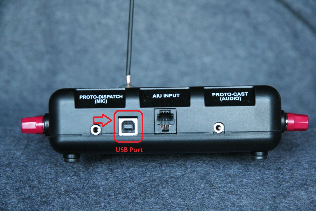
The Rev L TIU (with its enhanced track signal processor) has brought significant improvements in overall layout track signal levels. The unit has a faster system processor and includes a USB port for connectivity to your personal computer. In addition to providing connectivity to the PC, the USB port now also provides the power you need to the TIU for performing functions such as firmware upgrades to the TIU and remote or upgrading sound files in engines. (The original 9 pin Serial port is still provided if you want to continue to use it.)
With the exception of the USB port (and Rev L label on the bottom), the TIU looks identical to the previous TIUs.
Testing of the TIU's Enhanced Signal capability:
My testing has shown a 2-4x improvement in track signal levels when run with engines equipped with the older Protosound 2 boards. (It should be noted that the new Protosound 3 board alone provide a significant improvement in signal levels and when used with the Rev L TIU those improvements are that much greater.) The enhanced signal processor has made a significant impact in raising overall track signal levels and increasing the total number of linear feet of track a single port can signal.
Based on my experience in deploying a 1600ft oval for the World's Longest Train attempt in 2011, the number of liner feet a single TIU channel can successfully signal is in excess of 1600ft under DC power even with the older PS2 equipped.
Actual test results: (With the older PS2 equipped engine)
(Click to image to enlarge)
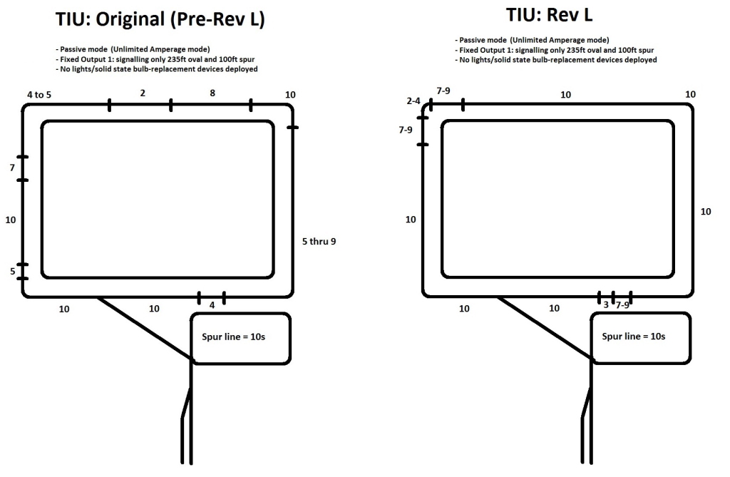
As you can see from the above image (testing with older PS2 engine), the original pre-Rev L TIU provided acceptable signal even without the need for lights/SSLT(Solid State Layout Tuners), but the new Rev L gave near perfect results. Since my preference is to see perfect 10s on a signal test (even in cases like this where there is no operational need) I deployed 2 lights/SSLTs at the track level and achieved perfect 10 signaling everywhere.
As a second test I ran both ovals with a single TIU port (instead of using 1 Fixed port per oval) and found the results remained constant with no reduction in signal. These tests show that even with Stainless Steel track, 600ft of track can be signaled with one TIU port with minimal provisions.
With the new Protosound 3 boards that are out signal levels are significantly better than above.
For the World's Longest Train attempt in 2011, I was able to successfully signal a 1600ft oval with the TIU in Passive mode with older PS2 engines: WLT - DCS Signal Test (WLT page: Worlds Longest Train - 2011 )
Conclusion:
What this means for the user is that with the introduction of the new Rev L TIU, a single $179 TIU can signal more track than most users in the hobby have on their layouts and when running the TIU in Passive mode (unlimited amperage mode) users can run/control as many locomotives and lighted passenger cars as their power supply allows because there are no amperage limitations with the TIU.
Also now with the introduction of Protosound 3 track signal/communication is far more robust.
____________________________________________________________________________________________________________________
Use of TIU to provide signal to track: Normal vs Passive mode:
While not commonly discussed or documented, there are two ways to provide DCS signal to the track, Normal mode and Passive Mode.
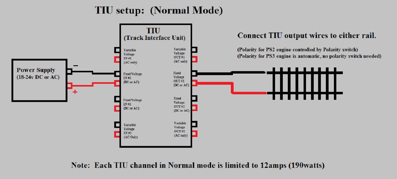
Normal mode:
Using your TIU in normal mode is simply running the + & - outputs from your power supply to the input terminals of the TIU and connecting the wires from the track to the TIU output terminals. Running in this configuration can sometimes provide a little better signal strength as opposed to passive mode (noted below).
Running in normal mode however does impose limitations. Each TIU channel is rated at 12amps/190watts (24v max), so for larger layouts with higher amperage draws (like can be found in G scale), 12amps can be used up quickly with a 10+ car lighted passenger train or two. And if you have a loop large enough to run more than one lit passenger train, you will either need to break your loop into blocks and use more than one channel or come up with another solution...and that's where running the TIU in passive mode comes in. Also when you run in Normal mode it is important to use an inline fuse to protect the TIU from shorts that may occur on the layout.
TIU output ports: If using more than one TIU port on layout, the wires/tracks that they are connected to must be electrically isolated from each other.
Example: Normal Mode
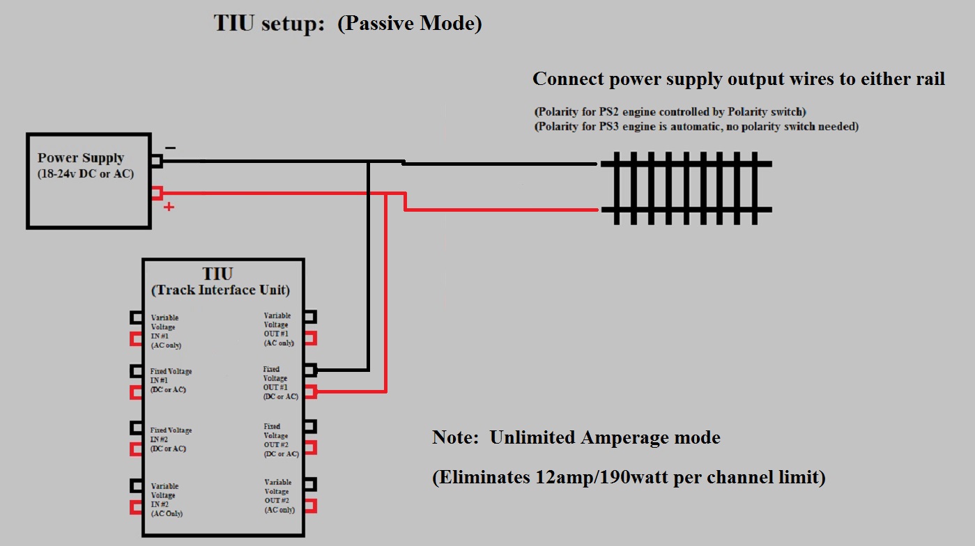
Passive mode:
Passive mode means running the + and - outputs from your power supply to the OUTPUT terminals (NOT the input) of the TIU, then running your wires to the track from where the wires meet on the output side of the TIU. By running in this configuration, you aren't running power through the TIU and therefore have no limits on the amount of amps you can provide to the track for a given TIU port. Compared to Normal mode you may or may not see any changes in track signal levels. Do note that this does mean that you can provide power to the track with your power supply from one location and connect the TIU output terminals to the track in a completely different location (The TIU connection does not have to be tapped into the wires going from the power supply to the track).
Also note that you do not need to provide power to the TIU via the Fixed 1 INPUT port OR via an aux power supply as long as you apply power to the OUTPUT terminals on the Fixed 1 port. The TIU will still get the power it needs to function when power is applied to either the INPUT or OUTPUT terminals on the Fixed 1 port. (Please note I always recommend that you do not power the TIU via its Aux power input.)
When you run the TIU in passive mode, the TIU is automatically protected from shorts on the layout as power is not being passed through the TIU. It is still recommended to use an inline fuse in the Positive wire from the power supply.
Example: Passive Mode
Mike's Train House MTH DCS Protosound 2 Protosound 3
____________________________________________________________________________________________________________________
Protosound 3: (What's new with PS3 vs PS2)
Protosound 3 was introduced in MTH locomotives starting in 2011 for O Gauge and made available as an upgrade for older PS2 engines as of Jan 2016. (Note: HO scale engine have been PS3 since inception in 2008)
Feature/Enhancements list for new MTH Protosound 3 boards:
PS3: (Factory pre-installed in MTH Engines)
- Can use both original PS2(3v) or new PS3 sound files.
- Increased memory capacity for sound files (higher quality sound)
- Higher quality audio amplifier (vs PS2) for crystal clear sound reproduction
- All LED lighting instead of Incandescent. (saves power and longer bulb life)
- If power is temporarily lost to engine, LED lights stay lit, powered by on-board capacitors.
- Auto 'Rule 17' lighting of the headlight (auto dims when idle for a period of time and brightens back up when commanded to move)
- Eliminates the need for a polarity switch on the engine
- Has significantly improved communication signal processor for better track signal.
- You will get improved signal strength with all TIU versions. Best results with Rev L TIU or newer.
- Eliminated the rechargeable battery pack (uses built in capacitors for backup power)
- Can be run and controlled in a DCC environment (DCC power and control) with the flip of a switch on engine/tender. See the below link for more info on DCC PS3:
- www.rayman4449.com/DCS_Overview_Videos.htm#Operating_PS3_Under_DCC
- Engines now no longer take off running if they miss the TIU initial power up signal. (An issue when running under DC power) If an engine misses the signal it will power up lights and sound but stay put and not move.
- Because of the improved signal processor, missed TIU startup signals will be eliminated or greatly reduced.
PS32: ("PS32" Upgrade board for PS2 to PS3 upgrades) ** Different from Factory PS3 board
- Can use both original PS2(3v) or new PS3 sound files.
- Increased memory capacity for sound files (higher quality sound)
- Higher quality audio amplifier (vs PS2) for crystal clear sound reproduction
- **All connectors same as the PS2(3v) board to simplify upgrade.
- **Drives original Incandescent lights to simply upgrade from PS2 to PS3.
- **Does not currently have Auto 'Rule 17' lighting of the headlight (auto-dimming when idle for a period of time and brightens back up when commanded to move)
- May be made functional in later PS3 board firmware versions.
- Eliminates the need for a polarity switch on the engine.
- Has significantly improved communication signal processor for better track signal.
- You will get improved signal strength with all TIU versions. Best results with Rev L TIU or newer.
- Eliminated the rechargeable battery pack (uses built in capacitors for backup power)
- Can be run and controlled in a DCC environment (DCC power and control) with the flip of a switch on engine/tender. See the below link for more info on DCC PS3:
- www.rayman4449.com/DCS_Overview_Videos.htm#Operating_PS3_Under_DCC
- Engines now no longer take off running if they miss the TIU initial power up signal. (An issue when running under DC power) If an engine misses the signal it will power up lights and sound but stay put and not move.
- Because of the improved signal processor, missed TIU startup signals will be eliminated or greatly reduced.
Other notes:
- PS3 engines are fully backward compatible with all existing TIUs and Remotes.
- PS3 boards use chips and components that are more easily sourced on the market which will ensure there are never supplier constraints in the future. (i.e. should never be issues with getting PS3 board / upgrade kits in the future once they start making them)
- All current production MTH engines are being made with PS3 installed.
- PS3 is available for HO, O, One Gauge and S. (Boards for HO are different from O/One Gauge and are designed to accommodate the reduced space and amperage requirements of HO.)
- All current production MTH One Gauge engines (2013 Catalog and newer) will come with PS3 pre-installed.
- The O gauge PS3 and PS32 boards were made with the One Gauge line in mind so no special provisions should be required for One Gauge.
G scale/One Gauge Specific Notes/Key Benefits:
- Significantly improved signal processor on the engine board. (If you have had signal/communication issues in the past on your layout, this should resolve it or significantly reduce any issues. Best results, run PS3 with Rev L TIU)
- This is relevant for G scale because of the much larger size of the layouts and conditions faced outdoors.
- Improved audio amplifier for higher sound quality
- PS3 sound sets have greatly enhanced sound quality.
- No more missed TIU start up signals: Engines stay put and will not move if they miss the TIU startup signal on initial power up. (Applies to DC power operation)
If you had engines missing the signal in the past moving to PS3 should eliminate or greatly reduce this happening.
- Eliminates the need for the polarity switch on the engine as the PS3 board is no longer polarity sensitive.
- Eliminates the need for the on-board rechargeable battery pack (the only maintenance item you had on the engine)
- Can now run under DCS or DCC.
Discuss on Gscaletrainforum.com: What's new with MTH's PS3 vs PS2
Mike's Train House MTH DCS Protosound 2 Protosound 3
____________________________________________________________________________________________________________________
Wi-Fi Interface Unit (WIU)
The Wi-Fi Interface Unit has been developed my MTH Electric Trains to allow the control of MTH Protosound 2 & 3 equipped locomotives via any Android/Apple iOS smart phone or tablet. The WIU is an separate box that connects to the MTH TIU (Track Interface Unit) and can be connected to the TIU via USB cable (if TIU is Rev L or newer) or by RS-232 (9-pin) Serial port. (Serial port connection requires USB to Serial adapter cable that is sold separately *Purchase USB to Serial cable*)
Items related/required for using new WIU & App:
- Android/Apple(iOS) App: (Available for download via the Apple iTunes and Google Play online stores.)
- Free version: Controls up to 3 locomotives w/limited light and sound control (Available now)
- Standard version: ($4.99 cost) Controls up to 99 engines and more sound/light control settings. (Available now)
- Premium version: ($24.95 cost) Provides Lash-ups and switch/accessory controls. (Expected Release April 2016)
- WIU (Wi-Fi Interface Unit): Now available to purchase (Click here to purchase: Buy WIU)
- Note: WIU comes with USB cable for direct connection to the latest Rev L TIU that has USB port. If you have older TIU you will need a serial to USB adapter cable
(Purchase serial to USB cable here)
- TIU (Track Interface Unit): (Available separately or as part of DCS Control set with DCS remote) (Purchase TIU here / Purchase DCS Remote Control Set here)
- w/TIU version Rev L (Latest version with USB port): Will work with your WIU without any extra cables to buy.
- w/TIU versions older (Rev G, H, I etc): Need to purchase a serial to USB adapter cable (Purchase serial to USB cable here)
- MTH DCS version 5.00 or greater (Required for TIU) - Now available (See this link for help: Help on upgrading TIU/Remote to latest DCS version)
- Link to Updated DCS Consumer Loader program for your Windows PC: www.gscaletrainforum.com/index.php?/topic/694-mth-dcs-consumer-loader-v500-current-version/
- Link to current DCS v6.00 for TIU & Wireless remote www.gscaletrainforum.com/index.php?/topic/693-mth-dcs-remote-tiu-firmware-v600-current-version/
Wi-Fi DCS User's Guide: (Download from MTH)
- Addendum to Guide:
- Multiple WIUs (Connecting via Ethernet cable): To setup do the following for each WIU -- Connect the Ethernet cable from your home router/network, USB cable from TIU to WIU, attach Antenna, leave switch set to MTH, and plug in the WIU power cable. When the app first starts it looks for available WIUs. Hit the Refresh button once for every extra WIU you have on your network. (ie Press refresh once if you have 2 WIUs) Your active engine list will now be updated or you can now add engines and run trains.
Issue and bug reporting:If you find an issue or bug with the app please post here and the feedback will be shared with MTH: www.gscaletrainforum.com/index.php?/topic/727-mth-wifi-control-wiu-feedback-issue-reporting/#entry6258
Demo & Overview of the Wifi app: (Standard version) (Select 1080p HD to get max playback quality)
Note: The Refresh button (see GREEN arrow) that allows you to do a search and update your active engine list.
.jpg)
Wi-Fi Interface Unit overview: (Click image to enlarge)
**Buy Wi-Fi Interface Unit (WIU) HERE**
____________________________________________________________________________________________________________________
Tuning your Layout: (Deploying Light Bulbs/SSLTs to Maximize Track Signal & Communication)
The final step to maximize your layout signaling is to tune it using Light Bulbs or SSLTs (Solid State Layout Tuners) deployed in two distinct areas/steps:
- TIU outputs/Distribution blocks (Only applies if you are using an older pre-'Rev L' TIU. If using Rev L TIU, ignore this item)
- Track level on the layout itself at various points (Applies with all TIUs and situations and will be the most effective step)
TIU Outputs / Distribution block Tuning: (Deploying Light Bulbs/SSLTs) (***Applicable only for the older pre-'Rev L' TIUs***)
This involves the use of a single light bulb (or SSLT) on each output of the TIU. (see Lights/SSLTs for bulb types to use.) This simple application makes a significant improvement in the overall signal effectiveness. (You will want to utilize bulbs with a relatively higher amperage rating of .2 amp or more. The lower the amperage rating the more you will need to gain needed effect.)
Track level Tuning on the Layout itself: (Deploying Light Bulbs/SSLTs)
The use of lights/SSLTs at the track/layout level can have a significant effect in your overall layout track signaling levels and resolving any areas you might have track communication issues. (For info on new SSLT see: Solid State Layout Tuner)
Note: Before you do anything, Locate TIU in a position above the layout (about 12 inches or more) and mount horizontally. (This can increase track signal levels on the layout)
To tune the layout at the track level, there are two steps:
1) Use light bulbs with a high amperage rating or use the new SSLT.
2) Deploy them in the correct method for maximum effectiveness.
Step 1: Select light bulb or SSLT
Light Bulbs:
You can use any bulb with a voltage rating at least as high as the voltage you intend to use on the layout. The amperage of the bulb will determine how many you will need to use and recommend using bulbs with a .2 amperage rating. Make sure you acquire a bulb that has an adequate rated life.
SSLTs: (Solid State Layout Tuners)
The SSLT is a new device that replaces the light bulb. It has an unlimited life, produces no light and is fully weather proof which is perfect for outdoor layouts. See this section for more info: SSLTs
Step 2: How to use/deploy (Light bulb/SSLT)
Generally for ovals over 150ft I have found it beneficial to deploy a total of 4 lights/SSLTs at the track level (1 at each of four points) around each oval, equal distance from each other. This covers most layouts, under most conditions.
If you have really large ovals or still have an area of track that you want to try and improve signal test levels I recommend the doing the following:
Park the engine in the area with the reduced signal or control issue and start the track signal test (to start track signal test, on your remote go to MENU -> SYSTEM -> TRACK SIGNAL) (if you have more than one area of reduced track signal, start with the area with the lowest level first)
Note: If you have engines on your layout that are equipped with Protosound 2 (as opposed to PS3), then use a PS2 engine for this process. If you do this process with a PS2 engine (which will report lower signal levels in tests vs PS3) then you will have your layout set for any engine type.
Go to the opposite side of the oval from where the engine is and connect light/SSLT one at a time and watch for improvement on the signal meter. (Usually only need 1 but sometimes 2 offers a little more benefit).
For 2-rail track: Connect one side of the light/SSLT to one rail and the other side to the other rail
For 3-rail track: Connect one side of the light/SSLT to the center rail the other side to one of the outer rails.
If you still want to improve the signal levels then proceed to other points halfway between there and the engine on either side of that point and try test deploying again.
Next, stop the signal test, start the engine moving, them restart the signal test and check signal around the track.
That should be all that's needed. Once you gotten the signal where you want it, you will never have to change the deploy locations again.
REMEMBER: My procedure for tuning the layout assumes you have each loop as a continuous electrical loop at the track/rail level. If your ovals/rails are electrically insulated and broken out into electrical blocks (and/or have continuity breaks at the switches) then attempts at tuning your layout will be a individual trial and error process and can't be sure of the level of effectiveness. With ovals in a continuous electrical oval, tuning is an easy and repeatable process and is highly effective.
Note: If you haven't already done so, Locate TIU in a position above the layout (about 12 inches or more) and mount horizontally. (This can increase track signal levels on the layout)
Note: There has also been suggestions to use a 'filter' which comprises placing a 0.1uF(100v) solid state capacitor and 221ohm resistor in series across the rails at the terminating point of a given power block (ie. Power connector at one end of block and filter on the other end). In my testing, I have found these filters do not work as well as the light or SSLT and do not recommend their use. While some may have found benefit from their application, I have found no replacement for the rock-solid performance of the light/SSLT. Lights/SSLTs can be used in any wiring configuration and eliminate any/all symptoms of track signal communication issues, the filters do not.
____________________________________________________________________________________________________________________
SSLTs - (Solid State Layout Tuners):
A replacement for the light bulb is now available that are fully water/weather-proof, have an unlimited life and are easily placed between the rails (on G scale track) with no special tools (O gauge will require some soldering). They are black in color so as not to stand out and can be mounted so they can be covered in ballast so they can't be seen.
Each pair is the equivalent of one light and in most cases for a simple oval you would only need one pair but you might want to get a couple just to be sure.
Sold as set of 5: $8.00
To order - email:
How to use/deploy:
If have an area of track that you want to try and improve signal test levels, I recommend parking the engine in the area with the reduced signal or control issue(if you have more than one area of reduced signal start with the area with the lowest levels), start the track signal test, and then test deploy lights/SSLTs one at a time. Start by deploying one at the opposite side of the oval from where the engine is, then proceed to other points halfway between there and the engine on either side of that point. If you see improvement with one deployed try a adding another to see if you get additional improvement. Move to the other half way points only if you have reached the max improvement but still want more. Otherwise, stop the signal test, start the engine moving, them restart the signal test and check signal around the track. If you have a second area of lower signal you want to improve. Note the location, stop the test, then stop the engine there. Restart the test with the engine in place and test deploy the lights/SSLTs in the already noted way. Once you gotten the signal where you want it, you will never have to change the deploy locations again.
REMEMBER: My procedure for tuning the layout assumes you have each loop as a continuous electrical loop at the track/rail level. If your ovals/rails are electrically insulated and broken out into electrical blocks then attempts at tuning your layout will be a individual trial and error process. With ovals in a continuous electrical oval, tuning is an easy and repeatable process.
Note: If you haven't already done so, Locate TIU in a position above the layout (about 12 inches or more) and mount horizontally. (This can increase track signal levels on the layout)
____________________________________________________________________________________________________________________
Passenger or Freight cars with lights:
I have found that longer runs of fully lit passenger train (over 6 to 8 cars) can result in reduced signal levels when a signal test is run on the lead engine. I've found that adding a small inductor (Choke Coil) on the positive and neg lead wires going to the lights on each car eliminated any change/reduction in signal levels. (Suggest using a 100uh or greater) I have since added them to all my passenger cars.
Here is a write-up on how I installed them in my Aristocraft Heavyweight & MTH passenger cars:
Adding inductors to get better MTH DCS track signal in Aristocraft Heavyweight passenger cars
Adding inductors to get better MTH DCS track signal in MTH Passenger cars
Comments in the O gauge community after the Rev L TIU release seems to show little to no benefit in the use of inductors for lighted passenger cars. Some preliminary testing in G scale under DC power have shown that there can still be a benefit to adding them. Again, most may not see any need to add them to their passenger cars, but be aware if you start seeing an effect with long lighted trains then this is something to consider implementing.
Note: If you haven't already done so, Locate TIU in a position above the layout (about 12 inches or more) and mount horizontally. (This can increase track signal levels on the layout)
If you would like to purchase some inductors for you passenger
cars please email me at:
____________________________________________________________________________________________________________________
II. Engine / Remote / System operation:
Quick summary checklist: Operational / DCS System setup:
- Use correct type of track power:
- MTH O gauge/S/One Gauge/Tinplate/Upgrades kits boards: Protosound 2 & 3 can use DC or AC power (18v-24v max)
- MTH HO: Protosound 3 is DC power only (18v max)
- MTH HO: Protosound 3E+ is DC or AC power (3 rail HO) (18v max)
- Fuses **IMPORTANT**
- Ensure you have a Fuse inline on the positive wire between the transformer and TIU/Layout. (Use a maximum of 10amp fuse for each port if running TIU in normal mode)
- See Using Fuses for more info
- Power supplies: **IMPORTANT**
- Please read through this section: http://www.rayman4449.com/DCS_Tips.htm#Type_of_Power_Supply
- DO NOT USE:
- Power supplies with Pulse Width Modulation/Pulse Width Control (PWM/PWC)
- Bridgewerks "Mag 15" direct connected to the track or TIU (Mag 15-R is safe to use)
- Determine if you want to connect the TIU to the track in Normal mode (12 amp/190watt limit per port) or Passive mode (unlimited amperage mode)
- Determine which TIU Ports you want to use. (see Which TIU ports to use for more info)
- Determine how you plan to power the TIU. (see How to provide power to the TIU for more info)
- Ensure you have polarity correct between the: 1) Power supply and TIU (issue applies only for DC power) & 2) TIU and engine (issue for PS2 only) (see Polarity to TIU & Engine for more info)
- Power supply to TIU polarity (an issue with DC Power supplies only) can be corrected by flipping the direction button on your DC transformer.
- (PS2 only) TIU to engine polarity can be corrected by flipping the polarity switch that is installed on the engine. (If you have an MTH One Gauge Challenger or Hudson that does not have a polarity switch then flip the wires on the TIU output terminals or put the engine on the track the other direction.) (Note: Polarity at the engine is only applicable for PS2 engines only, PS3 does not require polarity switch)
- Check DCS remote and TIU software versions. Make sure you are using 3.11, 4.10 or greater. (6.10 is most current)
- If using a TIU older than 'Rev L' (i.e. with lower letter) connect an incandescent light bulb to the output of the TIU Fixed 1 port(s) (and Fixed 2 if you are using it).
- If you're using a 'Rev L' or newer TIU incandescent lights are not needed on the output ports.
- Check voltage with voltmeter to ensure your DC or AC power supply is putting out between 18-24v. (Too high a voltage can result in faulty operation and possible damage to system.)
- Note: Regardless what voltage you decide to apply to the track, it will not affect (help or hurt) track signal levels in any way.
- Note: The only effect of running a DCS equipped engine (with the TIU & Remote) on track voltage levels lower than 24v will be to limit it's top speed.
- If your power supply (DC power) has a momentum button, turn it off if you are using it with TIU, DCS Explorer or other MTH digital control.
- If using a power supply with a throttle, use the Throttle output terminals (or "To Track" posts on a Bridgewerks) instead of fixed voltage output ports. (See photo BW Throttle)
- Preset the power supply throttle to 18-24v, then turn the power switch to ON. (I don't recommend increase the throttle from 0 to 18-24v.)
- Do not turn the power supply ON then turn the voltage up from 0v to 18/24v too slowly. (It can cause the engine to miss the TIU startup signal and power up in Analog mode)
- If you have the polarity wrong and have to correct by either flipping the direction button on your transformer or polarity switch on the engine, you need
to turn the power off, change the polarity, then turn the power back on. Failing to cycle the power on the power supply will result in the engine not responding.
- If you have track signal issues in some areas and have delays in the remote response time due to error messages ('Check track' / 'Out of RF range'), set your remote to 'Speed'
operation. (Go to MENU -> SYSTEM -> REMOTE SETUP -> OPERATING MODE -> Select 'SPEED')
- You may also want to turn-off remote messages to further speed remote operation: (Go to MENU -> SYSTEM -> REMOTE SETUP ->
REMOTE MESSAGES -> Select 'OFF'.
- TIU Location: Locate TIU in a position above the layout (about 12 inches or more) and mount horizontally. (This can increase track signal levels)
- Once you have an engine running, do a 'Track Signal' check with the engine running around the layout to see if you have areas of reduced track signal that you might want to try and improve.
- See How to wire your layout & also Tuning your Layout with Light bulbs/SSLTs
- Make sure the DCS signal is turned on for each of the TIU ports you are using. (Go to MENU -> SYSTEM -> DCS SETUP)
- Remember, you press the thumbwheel down to select a highlighted option.
- If you have an MTH steam locomotive or diesel with tether cable, the wire will be pointing up from the plug when plugged in, DO NOT force the plug in upside down with the wire facing down. (See photo)
- Analog AC/DC operation: (without TIU connected to power supply or track wiring)
- PS3 engines:
- When you first apply power to the track, the engine will power up (Lights/Sound and/or Smoke) but engine will not move.
- To get the engine to move, turn voltage down to zero with your throttle, then back up and then the engine will move.
- AC power: Each repeating of voltage to zero and back up with change from NEUTRAL / FORWARD / REVERSE.
- DC power: To change direction you need to reverse track polarity with the DIRECTION switch on your power supply
- PS2 engines:
- AC power: When you first apply power to the track, the engine will power up (Lights/Sound and/or Smoke) but engine will not move.
- To get the engine to move, turn voltage down to zero with your throttle, then back up and then the engine will move.
(Each repeating of voltage to zero and back up with change from NEUTRAL / FORWARD / REVERSE.)
- DC power: When you first apply power to the track, the engine will power up (Lights/Sound and/or Smoke) AND WILL start moving at the selected track voltage levels.
- Remember if you have a reliable and solid foundation for a track powered layout, then you will have a solid foundation for running DCS.
- See: How to wire your layout
Error messages: (Quick reference)
- 'CHECK TRACK' = Engine on the track has not returned the confirmation that you just gave it a command. (Track signal issue or faulty equipment)
- 'OUT OF RF RANGE' = The remote is out of range of the TIU. The remote has not received a confirmation from the TIU you have issued a command to it/an engine.
(Can also be displayed because an engine did not respond to a command given by the remote.)
BASIC STEPS IN TROUBLESHOOTING operational/communication/control issues:
Polarity to TIU & Polarity to the engine: ('Polarity to engine' applies to PS2 only. PS3 is not polarity sensitive.)
By far one of the biggest issues when first getting familiar with operating the system is making sure you have 1) the power polarity set correctly going from the power supply to the TIU (this only applies if using DC power) and then 2) having the engine polarity switch set correctly (this applies for BOTH AC and DC power). So if you are having problems, the very first thing you should do is confirm you have both correct, starting with the TIU. Do this even if you think you already have it setup correctly.
Incorrect polarity to either the TIU or engine can lead to all kinds of issues:
Not able to 'start-up' your engine
Not able to add an engine to the remote
Getting Out of RF range errors on your remote (even with you standing right next to the TIU)
Polarity from power supply to TIU: (Step 1 of 2) ***Step 1 only applies if using DC power***
The first step is to ensure you have polarity between the power supply and TIU set correctly. Make sure you have the + output (for DC power supplies)/RED post (on AC power supplies) from the transformer going to the red port terminal on the TIU port and the - output (for DC power supplies) / BLACK post (on AC power supplies) to the black TIU port terminal. (See: Running TIU in Normal vs Passive mode for more information on wiring your TIU to the layout) If you have a Bridgewerks DC Throttle power supply, make sure you have direction switch on the power supply set to "FORWARD" (in the up position), then confirm the Red terminal on the "To Track" outputs on the power supply runs to the Red terminal on the TIU and the Black terminal on the power supply to the black terminal on the TIU. (See: Which TIU ports to use for more information)
Polarity to the engine (i.e. correctly set engine polarity switch): (Step 2 of 2) ***Applies if using either AC and DC track power** (Applicable only for PS2 engines, PS3 engines do not require a polarity switch and is not polarity sensitive)
*Please note that this section only applies to engines equipped with the older Protosound 2. Protosound 3 engine boards are not polarity sensitive so this does not apply. PS3 engines no longer require a polarity switch.*
Once you've confirmed you have the polarity from the power supply to the TIU correct (Step 1 of 2 above), you will then want to ensure the engine is getting the correct power polarity.
If you are using AC power then just make sure your RED terminal post on the TIU output port is going to the center rail of the track. If you are using O gauge 2 rail, then may require trial and error adding engine to the Remote/DCS app in Phone/tablet.
If you're using DC power, the easiest way to tell if the engine has the power polarity switch set correctly (see Polarity switch location on engine) is to listen to the number of clicks in the engine when you first apply power (you may need to put your ear down near the engine to hear it) If you hear 2 clicks (may sound like just one), then you know you have polarity to the engine correct and are ready to go. (Click here to listen to relay sound of Correct polarity to PS2 board under DC power) If you hear a series of clicks (3 or more) then the power polarity switch on the engine needs to be flipped to the other direction. (Click here to listen to relay sound of Wrong polarity to PS2 board under DC power) (Note: If you find that you need to change the polarity switch direction, be sure to turn off the power supply and power back up after changing the polarity switch.)
If you are running under AC power, you will hear only two relay clicks in both correct and incorrect polarity. So if you have Power supply to TIU polarity confirmed to be correct and you are having problems starting up or adding the engine to your remote you will need to flip the polarity switch on the engine and try again.
Note: You may find some/most O gauge 3 rail engines don't have a polarity switch, in which case you will just need to ensure RED post on TIU output goes to center rail. For One Gauge/G scale, a very few original production run One Gauge Challengers, Hudsons and Dash-8s did not come with polarity switches. This means it will need to either 1) flip the wires going from the TIU to the track (if running TIU in Normal mode) or put the engine on the track facing the other direction in order to get the engine polarity correct. Remember if you are running the TIU in Passive mode (unlimited amperage mode), you will need change the polarity from the power supply to the track AND change the wires going to the TIU output ports.
Ensure TIU setup is correct in remote:
(Please note: Most users will be using just one TIU and out of the box your TIU and remote are set to work correctly. Just power up and go. If you are running more than one TIU or think you may have changed your TIU configuration by mistake then read on.)
Having the TIU(s) identified and setup incorrectly in the remote can also cause operational issues and unexplained error messages. Each TIU has an address number assigned to it. (by default it's set = 1) This TIU addressing allows the remote to know and properly communicate with multiple TIUs by allowing them to each have a unique number. When you run with more than one TIU at a time they must all have a different TIU address number.
Super TIU mode: If you are running with more than one TIU on a layout, you will want to set each one to Super Mode. Otherwise an engine added to a remote will only respond to commands when running on a channel for the TIU it was added on. If it goes to another loop or zone powered by another TIU, you will be unable to control it.
How to check your configuration settings and perform setup: (remember you need to press the thumbwheel down to 'select' an entry)
Check that all TIUs have a unique address number assigned to them
Confirm a TIU's address number
Turn the power on to the Fixed 1 port on the TIU with the top of the TIU visible. Note the Red LED that lights up. After about 3 seconds of being lit solid, it will blink. The number of blinks will indicate the TIU address. One blink = TIU address 1, Two blinks = TIU address 2, etc
Repeat this for each TIU you have. Each TIU should have a unique address
Change the address # stored in the TIU: (If needed)
Power down all TIUs.
Turn on power only to the Fixed 1 port of the TIU you want change.
Turn on the remote and select: MENU --> TIU SETUP --> EDIT TIU ADDRESS
Select the current address number for this TIU then press the thumbwheel.
Select the new address number you want this TIU to be and press the thumbwheel.
Power down the TIU and turn back on. Confirm the Red LED on that TIU blinks with the correct TIU Address count now.
Repeat this for each of the other TIUs you want to change.
(Note: If you have more than one TIU with the same starting address (say two with address=1) and you want to change both to another address, you will need to re-add the TIU address 1 in the remote in order to change the address on the second one.) Select: MENU --> TIU SETUP --> ADD TIU --> Then the current TIU address of next one you want to change (say TIU 1 in this example.) Now you can repeat the change TIU procedure.
Check that all TIU address numbers are identified/setup in the remote: (using the TIU address you confirmed from step 1 above)
To confirm the TIU(s) setup in the remote is correct:
Turn the power on to the Fixed 1 port on the TIU
Turn your remote on
With the remote, select: MENU --> SYSTEM --> TIU SETUP --> EDIT TIU ADDRESS: (Note which TIU address # entries you have listed on the remote screen.)
If you have an extra TIU listed in the remote:
Hit the MENU button again to go back a screen and select TIU SETUP --> DELETE TIU --> Select the extra TIU to delete
If you are missing a TIU address in the remote:
Hit the MENU button again to go back a screen and select TIU SETUP --> ADD TIU --> Select from the remaining TIU addresses left available that match the address of the missing TIU: "TIU 1, TIU 2, TIU 3, TIU 4 or TIU 5."
Repeat this for each TIU address number that you need to add.
Setting TIUs to Super TIU: (Once you have all TIUs identified in the remote)
Power up the TIUs then with your remote select: MENU --> TIU SETUP --> SUPER TIU --> Select the TIU address of each TIU and press soft-key S2 'SPR'.
Repeat for each of the other TIU address numbers and you are done.
'Out of RF Range' Errors - (even after proper polarity to TIU and engines have been confirmed):
This can be caused by at least five situations:
1) Have the remote too far away from the TIU
2) The RF board is loose in the TIU or remote
3) Engine did not respond to a command given by the remote
4) You have the TIU configuration setup incorrectly in the remote
5) You have the DCS signal turned off for that port
#1 - Have the remote too far away from the TIU:
This can be corrected by simply moving closer or moving the TIU to a better location. (If you need longer range, see the info on extending the TIU and remote range on this page.)
#2 - The RF board loose in the TIU:
This can mean you have an RF board loose in either the TIU or Remote. The TIU is easier to check and can be opened up by turning it over and unscrewing the six screws on the bottom. Lift the top of the TIU carefully up. Ensure the board in the second photo is pushed all the way down onto the main TIU motherboard.

If you suspect the remote board has come loose (which is not likely as it is adhered to the main remote board), see my TIU mods page for how to get the remote apart.
http://www.rayman4449.com/MTH_TIU_Mods.htm
#3 - Engine did not respond to a command given by the remote:
You may get this message ('Out of RF Range') when you've given an engine a command (via the remote) and the remote did not receive the confirmation response from the engine that it actually received the command. You can correct by resolving the underlying cause of the poor track signal or if you want to stop seeing these messages just set your remote to 'SPEED' Operation. (see Eliminate delays in remote response time and improve engine response/control in areas of bad track signal for more information)
#4 - You have the TIU configuration setup incorrectly in the remote:
If you have the TIU configuration setup incorrectly in the remote the remote could be attempting to communicate with a TIU address that doesn't exist. This can cause intermittent 'Out of RF range' errors and result in poor remote response time with the engine. (See the TIU configuration section above on this page.) (If you just have one TIU and one remote, you can just do a factory reset on the TIU and the remote and this should get you back to the default configuration.)
#5 - You have the DCS signal turned off for that port:
This is situation will not occur unless you've changed the settings in the remote as by default all ports will have DCS signal set to 'ON'. If you have a situation where you enter a dedicated 'block of track' that is supplied by a separate port on the TIU and you lose all control of the engine and get "OUT OF RF RANGE" errors, then check to make sure you have the DCS signal turned on for all ports. Go to MENU -> SYSTEM -> DCS SETUP and select each of the ports that you are using and press the S1 soft key for ON. (I would go in and ensure all ports have the DCS signal set to on while you are there.)
____________________________________________________________________________________________________________________
The DCS manual that comes with your TIU and remote can help provide guidance on which ports to use. (You may also want to see: DCS Overview Video series on the DCS Overview page for more information)
TIU output ports: If using more than one TIU port on layout, the wires/tracks that they are connected to must be electrically isolated from each other.
Each TIU has four ports:
- Variable 1 (Input & Output) -- For use with AC power only, does not function under DC power
- Fixed 1 (Input & Output) -- For use with either DC or AC power
- Fixed 2 (Input & Output) -- For use with either DC or AC power
- Variable 2 (Input & Output) -- For use with AC power only, does not function under DC power
Fixed ports 1 & 2:
If you're using DC power, these are the ports you have to use. If you are only going to use one port (and aren't using a separate Aux power supply to power the TIU), then be sure to use the Fixed 1 port. If you don't have an Aux power supply for the TIU you must have power going to the Fixed 1 ports (If running in Normal mode run power to the Input port terminals, if running in Passive mode, run power to the Output port terminals... See Running TIU in Normal vs Passive mode for more information.)
If you plan to run a separate oval or track then you will want to run separate feeds from the power supply to the Fixed 2 ports. (See Running TIU in Normal vs Passive mode for more information.)
Variable ports 1 & 2:
As noted above the Variable ports can only be used if you're using AC power. Since most of us running Largescale engines use DC power supplies you will not be using these ports. If you do run AC power and chose to use these ports, you will have one additional capability that you don't have with the Fixed ports which is the ability to vary the track power voltage to the Variable output terminals with the remote. You will want to make sure that your engines are able to run on AC power before doing this. I would not attempt to use a standard non-MTH Largescale engine and control it under AC power, damage to the engine may result.
If you plan to only run AC power and only use the Variable ports, you will need to ensure you either have an Aux power supply to power the TIU or run a set of wires from the power supply to the Fixed 1 input port terminals.
____________________________________________________________________________________________________________________
How to provide power to the TIU: (Aux power port vs Fixed 1 ports)
The first thing to know about the TIU is that it needs power itself in order to function and must be powered via one of two ways:
1) Providing power to the Fixed 1 port(s): The TIU can get the power it needs to function from the track power via the Fixed 1 port(s). (In Normal mode the means it will get power from the Fixed 1 INPUT port, if TIU wired in Passive mode it will get power from the Fixed 1 OUTPUT port. (See Running TIU in Normal vs Passive mode for more information on how to wire/run the TIU in Normal or Passive mode. This determines whether power is run to the input or the output side of the TIU.) (Note: I run my TIUs in Passive mode (unlimited amperage mode))
OR
2) Provide power via the Aux power input port on the TIU: This requires a separate dedicated 12-24v power supply be plugged into the side of the TIU. The Aux power supply can be either AC or DC power and should provide between 12v-24v and provide at least 1 amp. (Some sources recommend 12-22v)
Which should you choose? (The Aux power or Track power via Fixed 1 port)
If using AC power:
The Aux power supply is a good option, especially if you are using more than one TIU channel. If you are using more than one channel and you need to power down the Fixed 1 channel, if you dont have the Aux port the TIU will power down meaning you won't be able to send digital controls to engines on the other channels. When using AC power any time track power is cut off then turned back on, the TIU will resend the watchdog signal (necessary for commanding all DCS Protosound engines on the layout to remain shutdown and await commands from the DCS Remote).
If using DC power:
I strongly recommend against using the Aux power supply to power the TIU if using DC power.
When using an Aux power supply, anytime the power supply is shut-off or power to the layout is interrupted due to a short of blown fuse, the TIU will not power down. As a result, when track power is restored, the watchdog signal (necessary for commanding all DCS Protosound engines on the layout to remain shutdown and await commands from the DCS Remote) will not be sent! This means that all DCS Protosound engines will automatically power up in analog mode. (If you have PS2 engines, the engines will start off and take off running at full speed on their own, if you have PS3 the engines will power up but remain stationary and won't movie.
Note: To summarize, the only difference between these two methods of powering the TIU is:
If using the Fixed 1 port to power the TIU: The TIU will power up and down with the layout track power going to Fixed 1 channel.
If using the Aux port to power the TIU: The TIU will not power down if track power is cut to Fixed 1.
If using AC power: Each channel will resend the watchdog signal each time that channel's track power is turned on.
If using DC power: Each channel will not resend watchdog signal each time that channel's track power is turned on.
There are no other differences in using the Aux port.
____________________________________________________________________________________________________________________
Polarity switch location on engine: (Applicable to PS2 engines only. PS3 engines do not require polarity switch)
The polarity switch on MTH One Gauge engines will be located either under the cab or inside the smoke box accessible by opening the smoke box door.
Locations on various MTH One Gauge engines:

Big Boy
GS-4
Hudson
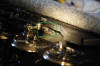
Triplex
Note: Early run Challengers may not have a factory polarity switch installed.
Listen to Correct and Wrong polarity sound to PS2 engine board under DC power:
- Relay sound of Correct polarity to PS2 board under DC power
- Relay sound of Wrong polarity to PS2 board under DC power
____________________________________________________________________________________________________________________
Problems controlling engine ('Check track' message when giving engine command)
This may be something you will encounter depending on how your layout is deployed. DCS uses a 2-way communication between the TIU and engine. If you give the engine a command and you get "CHECK TRACK", the engine did not respond back to the TIU that a command was given. (Do note that the engine may still have received the given command.)
Some steps to perform if you are having control problems:
1) Perform a 'Track Signal' check with the engine running around the layout:
- Start the engine running at the desired speed
- Use the remote and press MENU -> SYSTEM -> TRACK SIGNAL
- Note the track signal levels as it goes around the track. You will see anything from '10'(best) to '1'(worst) to
"CHECK TRACK" which means the engine's return signal isn't making it back to the TIU.
NOTE: If you encounter low track signal levels or get "CHECK TRACK" during the test, please read through Section I (Signal Strength)
at the top of this web page. Read through all of it to get an idea on how to improve areas of trouble.
2) Ensure you have the DCS signal turned on for all TIU ports you are using:
- To confirm, with your remote select: MENU -> SYSTEM -> DCS SETUP. Then select each of the ports that you are using
and press the S1 soft key for 'ON'. (I would go in and ensure all ports have the DCS signal set to on while you are there.) Note
that by default all ports should have DCS signal set to 'ON'.
____________________________________________________________________________________________________________________
Engine powers up and starts
running when track power is applied, but you have the TIU in place and want to
use the remote to control
(Applies only to PS2, not PS3 engines)
When the TIU is first powered up, it sends out a 'watchdog' signal to the track to tell all just powered up engines that the TIU is in place and to await commands from the wireless remote.
There can be various situations/scenarios that can result in an engine not seeing the necessary watchdog signal.
Turning track power on/off to the layout (when powering the TIU with a separate dedicated Aux power supply)
Turning track power on to a siding or staging/feeder track when the TIU and layout are already powered up
Turning track power on/off to the layout (when TIU does not use Aux power supply)
1) Turning track power on/off to layout (TIU using separate dedicated Aux power supply):
If you are powering your TIU with an Aux power supply, the TIU will only send the needed watchdog signal to the layout when power is applied to the Aux port. Most users however want their TIU to send the watchdog signal each time the layout and trains are first powered up. If you want the TIU to resend the watchdog signal each time the layout is powered up, you will need to ensure that you do not use the Aux power port and instead power the TIU via the Fixed 1 ports. (See Powering the TIU via its Aux power port vs Fixed 1 ports for more info)
2) Turning track power on to a siding or staging/feeder track when the TIU and layout are already powered up:
When turning power on to a siding or staging/feeder track that has an engine on it when the TIU and layout are already powered up and running, you will need to make sure a watchdog signal is sent to keep that engine from auto-powering up into conventional track power mode (i.e. startup and take-off running).
You can trigger a watchdog signal two ways:
With the remote (by pressing the READ button)
Adding a DCS Remote Commander box to the siding (so the signal is sent automatically) **BUY A DCS REMOTE COMMANDER SET HERE**
For more information on adding engines to a layout from a siding, see How to add an engine to the layout when other engines are already powered and running
Note: If you have a siding that you will turn on/off I recommend getting adding DCS Remote Commander box.
3) Turning track power on/off to the layout (when TIU does not use Aux power supply):
When the TIU receives its power only via the Fixed 1 ports (and not using an Aux power supply) the TIU will automatically send the watchdog signal each time the power supply is turned on/off or when power is restored to the layout & TIU after a short/blown fuse. This is the most hassle free way to run your TIU/layout and how most users will want their TIU setup/powered. (See Powering the TIU via its Aux power port vs Fixed 1 ports for more info)
Other situations/random engines starting up and taking off: (Applies only to PS2, not PS3 engines)
Once you have confirmed your TIU is not using the AUX power, if you have a Protosound 2 equipped engine that automatically powers up just starts running on its own, this means the engine is not seeing the startup 'watchdog' signal the TIU is sending out. The vast majority of these cases occur because the engine is located in a spot on the layout where there is poor track signal. (Causes and fixes for poor track signal can be read up on in other sections of this page.) Again note, this is not an issue with PS3 equipped engines.
In most cases it will most likely be because of:
1) Poor tack / Power conditions: (caused by)
Using switching mode power supply (this reduces the number of feet of track you can signal without issues)
Trying to power too many linear feet of rail per TIU port (may need to deploy lights/SSLTS. Avoid using switching mode power supplies on larger layouts)
Slider joiners used instead of direct to rail track clamps that are making very poor electrical contact due to bad oxidation over time or is loosely fit
Heavy corrosion/oxidation at track joints
Very dirty or very corroded brass track
2) Very poor power pickup on an engine: (caused by)
Very dirty wheels / power pickups
Combination of owner having removed sliders and some other track or power pickup issue
Some other issue with the power pickup circuit paths on the engine. (broken wire, etc) (Unlikely)
3) Possible hardware problem with either the TIU or DCS board in the engine. (Unlikely)
____________________________________________________________________________________________________________________
Loss of all lights and sound on engine while still being able to control it:
This is an issue that I've only experienced a couple of times in many hours of DCS operation (when running switching power supplies), and that is where the engine you are running will complete loose all lights and sound. The only times I've ever seen this happen is when you are trying to send a command to an engine over an area of track with very poor signal strength (also more likely when using switching mode power supplies. The engine lights and sound will cut out, but stay running and still allows you control speed.
The way to fix this problem is to perform a reset of the engine (feature or factory) via the DCS remote. First, make sure you have the engine 'Started up' by stopping the engine then pressing #3 on the remote. Next attempt a 'Feature Reset' by going to MENU --> ADVANCED --> RESET ENGINE --> FEATURE RESET. Next, cut power to the engine and let it sit for about 60 seconds. Turn power back on and attempt to start-up the engine. If you still do not have sound or lights attempt to do the Feature reset again. If that does not fix it, do a 'Factory Reset' on the engine by going to MENU --> ADVANCED --> RESET ENGINE --> FACTORY RESET. Next, cut power to the engine and let sit for about 60 seconds. Turn power back on and re-add the engine to the remote. (as a factory reset deletes the engine entry from the remote.) Then start the engine up.
I've seen an engine require being reset twice before coming back to life, but making sure you let the engine sit for a full 60 seconds is key.
So if this happens to you, don't worry you can fix it. If this does happen more than once, then do understand this can be a sign you likely have signal issues that you may want to address. (Consider getting a Bridgewerks power supply, upgrading to PS3, and/or using SSLTs)
____________________________________________________________________________________________________________________
Intermittent loss of sound or complete loss of sound from engine:
If you are running your engine and the sound gets staticy or intermittently cuts out, then you may have a problem with the tender wire connection. A write up can be found at this link to correct this issue: Tender plug repair
____________________________________________________________________________________________________________________
Intermittent loss of power to engine while running:
This is most likely the result of some sort of power pickup problem. The times I've seen this are usually over a cross-over or switch and has pointed to the problem being with a power pickup slider.
The cause will vary depending on the engine you are having problems with:
GS-4s: Generally don't have enough of an overall total length from the first power pickup to the last causing the engine to loose power for a split second over an Aristocraft #6 switch that has an unpowered frog. (From the factory Aristocraft #6 switches do have powered frogs but I cut the power to mine) The solution here is unfortunately to add additional power pickups on the engine (or tender) or provide power to the frog.
Big Boy: The times I've seen this engine have power pickup problems is when the power transfer board under the rear drivers has a burnt out trace due to having previously experienced a short on the track. This effectively removes the front engine power pickups from supplying power to the engine. See this link for more information: (Poor Power Pickup / Engine Shutting Down Intermittently)
____________________________________________________________________________________________________________________
Sound cuts-off before shutdown sound sequence is finished when you cut track power:
This is a sign of a dead or dying DCS Board battery and will need to be replaced.
Another way to test this is plug an extra DCS light into the battery recharge port. If the light stays lit steadily for a period of time the battery is likely good, if it starts to get dimmer shortly after being plugged in then the battery is weak and should be replaced.
You can also check the battery voltage by using a voltmeter to probe the terminals on the battery recharge port. A new battery (NiCad 2.4v pack) that has been fully charged and has been sitting a few hours should read ~2.54 volts. If you get readings of 2.10 volts or lower after charging and letting sit a few hours, then it's time to replace it. Battery packs will last between 3-5 years.
____________________________________________________________________________________________________________________
'Engine Error' message when trying to add engine:
This may be an issue running under DCS 4.10. If you get this message, first make sure you only have one engine on the track. Then verify you have the power polarity from the power supply to the TIU correct and then the power polarity to the engine correct. (See this link for more information: - Polarity to the TIU / Polarity to the engine )
Once the polarity is confirmed correct, press the 'Read' button on the remote. If you have a 'Lash-up' engine name (or other engine) come up as the engine identified on the track, do the following: Press the "ENG" button -> "S/U"(setup) softkey -> "EDIT ENGINE" -> "EDIT ADDRESS" -> select the Lash-up/engine that came up on the screen -> then select another available engine ID. Now retry adding the engine to the remote. (Note: You can also choose to just delete the Lash-up, but this will require to to recreate the Lash-up) MTH was made aware of this issue (as of 2/26/2009).
(You may need to set the engine on a small isolated short length of track directly connected to the TIU and use this setup just for adding engines and/or loading sound files.)
____________________________________________________________________________________________________________________
'No engine to add' message when trying to add an engine that you know isn't currently added/identified in the remote:
This issue is similar to the Engine Error message above. If you go to add an engine and get 'No engine to add' message and you know the engine hasn't already been added in the remote, first make sure you only have one engine on the track. Then verify you have the power polarity from the power supply to the TIU correct and then the power polarity to the engine correct. (See this link for more information: - Polarity to the TIU / Polarity to the engine )
Once the polarity is confirmed correct, press the 'Read' button on the remote and see what engine comes up as being identified. If it's another engine listed, delete that engine and then retry the add MTH engine procedure. After you successfully add the engine, go back and re-add the original engine you just deleted. Like the 'Engine Error' issue above I think this may be an issue related to the new v4.10 software load.
(You may need to set the engine on a small isolated short length of track directly connected to the TIU and use this setup just for adding engines and/or loading sound files.
____________________________________________________________________________________________________________________
TIU will not power up or no power from a particular Fixed or Variable port:
You should never see this happen if you are using 10amp fuses between the power supply and the TIU, but you may have a blown internal fuse in the TIU if you see any of the following:
(Note: Some older TIUs do not have internal fuses.)
TIU run in Normal mode:
TIU will not power up when power is applied to the Fixed 1 port.
No power goes to the output port when power is applied on the input for that same port. (Note that if you are applying DC power to the input side of Var 1 or Var 2, you will not get power reading on the Var output ports as they only function under AC power.)
TIU run in Passive mode: (Note: if you always run the TIU in passive mode you should never blow an internal TIU fuse)
TIU will not power up when power is applied to the Fixed 1 port. (Means internal fuse is blown on the Fixed 1 port)
Not getting DCS signal from Fixed 2, Var 1 or Var 2.
(This assumes TIU is powering up ok from power applied to the Fixed 1 (input or output port) OR to the TIU Aux power port)
To test if the fuse is blown, setup TIU to run in Normal mode (run power from transformer to the input port) then check the output ports that you have power.
If you don't have power on the output ports you have a blown fuse. (Note that if you are applying DC power to the input side of Var 1 or Var 2, you will not get power reading
on the Var output ports as they only function under AC power.)
Photo of the internal TIU fuses: (Note they are the smaller type of blade fuse. "Mini ATM blade fuse")

Photo of an older version TIU that does not have internal fuses:
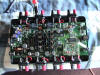
____________________________________________________________________________________________________________________
Ensure the DCS signal is turned to ON for the TIU ports you are using:
If you are having problems with an engine just starting up and taking off on power up or are losing control of the engine over an entire block of track that is using a different port on the TIU, verify you have the DCS signal turned 'ON' for all ports. With your remote, go to MENU -> SYSTEM -> DCS SETUP and select each of the ports that you are using and press the S1 soft key for ON. (I would go in and ensure all ports have the DCS signal set to on while you are there.) Note that by default all ports should have DCS signal set to 'ON'.
____________________________________________________________________________________________________________________
Eliminate delays in remote response time and improve engine response/control in areas of bad track signal:
If you have track signal issues in some areas and have delays in the remote response time and have trouble controlling engines (may be getting error messages 'CHECK TRACK' or 'OUT OF RF RANGE'), set your remote to 'Speed' operation. (Go to MENU -> SYSTEM -> REMOTE SETUP -> OPERATING MODE -> Select 'SPEED')
I found this eliminated any lag time between attempts at issuing commands and greatly improves overall engine response and control performance in those areas.
(Note: You may also want to turn-off remote messages to further speed remote operation: (Go to MENU -> SYSTEM -> REMOTE SETUP -> REMOTE MESSAGES -> Select 'OFF'.)
Of course just setting your remote to SPEED mode doesn't correct the underlying track level (TIU to engine) communication issue. If you want to correct the issue refer to the other areas on this page about ways to improve track signal.
*** If you do not have this option on your remote you will need to upgrade to a newer software version on the TIU and Remote. See Section V on upgrading and install the latest version. ***
____________________________________________________________________________________________________________________
How to perform a Factory Reset on an engine:
You can perform a factory reset two ways: 1) with the MTH DCS Remote & TIU set or 2) with WIU (Wifi Interface unit) & TIU using any Android or Apple iOS device.
Perform Factory Reset using:
MTH DCS Remote & TIU:
Ensure the engine is on the track and track power is applied.
Select MENU --> ADVANCED --> RESET ENGINE --> FACTORY RESET.
Note: If you are performing the reset to resolve an operational issue with the engine, cut power to the track and let sit for about 60 seconds. (You need to ensure you wait at least 30 seconds after all the sounds and lights have stopped. Turn power back on and re-add the engine to the remote then start the engine up.
MTH WIU (Wifi Interface Unit) & TIU & any Android/Apple iOS Device: *See this short overview video on WIU operation and functions*
Ensure the engine is on the track and track power is applied.
Start your Wifi App
Select 'Choose or Add an Engine' down arrow
Select the engine you want to reset
Select the Settings button/icon (3rd button with Gear icon)
Scroll down to Factory reset and Select.
Note: If you are performing the reset to resolve an operational issue with the engine, cut power to the track and let sit for about 60 seconds. (You need to ensure you wait at least 30 seconds after all the sounds and lights have stopped. Turn power back on and re-add the engine to the remote then start the engine up.
MTH DCS Remote Commander: (50-1033)
If the engine is PS3 it can be reset with the DCS Remote Commander itself by pressing the sound button [SND], followed by the direction button [DIR], and lastly [ - ] on the center rocker. (See instructions on Page 7 in the DCS Remote Commander Owners Manual (click the blue link))
____________________________________________________________________________________________________________________
III. Tips and Other Information:
USING A QUICK-BLOW FUSE - THIS IS A CRITICAL ITEM!:
The very first thing you should do before ever powering up your trains for the first time is to install a quick-blow fuse inline in the positive wire between the transformer and the TIU/Track. It is EXTREMELY important that you do not rely on your transformer's circuit breaker. Delicate electronics and power circuits can and will be damaged long before a breaker ever trips. You will want to make sure you run a fuse that most closely matches the load of the engines you are running. Also, the scale of the model trains you are running (HO, O, G scale) will affect the amp level of fuse you will want to use.
G scale/One Gauge:
- Ideally you will want to use a fuse rated about 3amps higher than the max load on the layout. Generally I recommend a 4amp fuse if running 1 maybe 2 MTH One Gauge Diesels engines, and perhaps a 5amp fuse if running an MTH One Gauge Big Boy, Challenger or Triplex)
Example: A typical MTH One Gauge Big Boy will use a max of 3 amps and in most conditions will use around 1 amp.
HO Scale:
- HO uses much lower levels of power and generally recommend most users start with a 2amp fuse. (Most HO users won't have ammeters (amp level meter).)
Example: If you have a 5amp power supply and run 1 HO engine, in an accident/derailment you will short 4+ amps through the engine's delicate wiring and electronics.
In many/most cases that can be enough to damage the engine wiring or electronics.
O gauge:
- Most O gauge users don't run with fuses although generally recommend the same for O gauge as G scale, consider a 5amp fuse (depending on the layout load).
Use your ammeter (amp level meter) to determine the load and to select the best amp for the job, I generally recommend a fuse that is about +3 amps above the peak amp draw you're seeing on your meter.
Use with MTH DCS TIU:
- If you are controlling your trains with MTH DCS Remote/TIU/Wifi, you will want the fuse/fuse holder located in the RED + wire between the Power supply and the TIU ports.
Do not install the Fuse between the TIU and the track/layout as you could affect/reduce the digital communication signals.
NOTE: If you start randomly blowing fuses don't just replace with a fuse that goes to (or above) the maximum output of your power supply. You need to first understand what is happening before doing this. If you are experiencing a short (either in the engine or caused by an engine on the layout) that is causing the fuse to blow, just jumping to a max fuse may result in the very damage you were trying to prevent by running fuses in the first place. Using fuses is a strategy to minimize the chances of problems/damage that can occur in the event of any sort of short event and requires active engagement/awareness to what is occurring on your layout.
Fuse holders:
I install two blade holders (in parallel) to allow the layout to remain running. Using two fuse holders allows the swapping out of fuses on the fly so there's no need to power down, swap a fuse, then restart all the engines again. Essentially, with two blade holders you have two separate power paths, so if you need to add a larger fuse and have a 5amp in one already, you can add a 7.5amp or 10amp fuse to the other fuse holder (now you will have power going through two holders) then pull the 5 amp.
Example of the blade fuse holder:
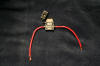

Example of two fuse holders wired in parallel (inline in the positive wire):
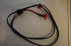
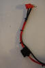
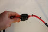
I have fuses available for purchase 20 cents each.
____________________________________________________________________________________________________________________
Improving the operating range of the wireless handheld DCS remote: (UPDATED 12/17/2010)
In typical operation, I've found the maximum range of the DCS handheld remote outdoors is about 50ft away from the TIU (especially with the TIU located inside house). I've also found the range can be extended significantly and have a page dedicated to this: MTH TIU Modifications
In short, by adding an additional length of wire to the short original antenna wire in the TIU for a total length of ~12.88 inches (which is the full wave antenna length for 916.5 Mhz) you can achieve ranges up to 300ft+ range (with the TIU located inside).
I do not recommend modifying the remote antenna setup.
See the provided link above for full information and photos. Bottom line, if you want to extend the range of your remote, you will want to make this modification.
Other things to ensure for maximum range:
- TIU placement: You may need to change where your TIU is located for best reception.
- Keep the TIU horizontal/flat if you need 360deg coverage around the TIU. (There may be some situations where mounting vertically on a wall works ok for you.)
- Use fresh batteries in your remote and use 1.5v alkaline. (1.2v rechargeables can result in a little shorter range, but is what I use. Do note that a freshly charged 1.2 volt can put out 1.5v and thus have similar performance as an alkaline.)
____________________________________________________________________________________________________________________
Track polarity: How to tell you have the correct polarity going to the engine: (Applies only to PS2, not PS3 engines.)
*Please note that this section only applies to engines equipped with the older Protosound 2. Protosound 3 engine boards are not polarity sensitive so this does not apply. PS3 engines no longer require a polarity switch.*
One item that can cause a lot of frustration when you first get started in DCS is applying track power in the wrong polarity to the engine (or having the engine's track polarity switch set backwards). The simple way to know whether the engine is getting the correct polarity is to listen to the relays click in the engine.
When you apply power, if you hear two clicks, it's the correct polarity.. if you hear a series of clicks, then it's backwards and you will need to flip the polarity switch on your engine. (See Polarity switch location on engine ) (Note that listening for a series of clicks for incorrect polarity is only valid if you are running your engine under DC power. If you are running under AC power, you will hear only two relay clicks in both correct and incorrect polarity)
Remember, you can have the power going to the engine in the correct polarity but still have the + and - backwards going into the TIU. This will still cause problems and you won't be able to get your trains running correctly. You may hear two clicks and think you're good to go but the engine won't respond, so check the TIU input polarity from the power supply. So always first make sure you have your transformer set to provide + to the red TIU port and the - to the black port. Then when you apply power listen to the relays and that will tell you if you are ready to go or not!
____________________________________________________________________________________________________________________
Track voltage levels and it's effects on DCS operation:
Different track voltages levels will not affect track signal levels or the ability of the engines to run at their correct scale speed (as is the case with DCC). Regardless of what track voltage levels you run with: 12v, 14v, 18v, 24v etc, the only effect it will have on a DCS equipped engine when running it with the TIU and Remote (under Command Control) will be to the engine's top speed. Running with 24v to the track will enable it to run at it's maximum top speed.
Track voltage levels will not affect the track signal levels in any way. You will not get better track signal at 24v as opposed to 17v or vice versa.
The voltage applied to the track also does not affect the performance of the dialed SMPH of the engines. If you have an engine dialed in to run 20 SMPH, that engine will run at the correct speed for 20 SMPH regardless of whether you have 17v to the track or 24v. If you are running the engine at say 20 SMPH with 17v applied to track and suddenly increase it to 24v, the DCS board will immediately compensate for the change in the track voltage (because it is monitored by the optical reader) and keep the engine running at the correct speed for 20 SMPH. (At some point you can reduce the track voltage to such low levels (like 9v) that it can achieve only a low maximum top speed.) Overall, what this means performance wise for you is as your engines run around the track, if they encounter any change in track voltage the engines will compensate for these changes and keep the engine moving at the correct speed. This allows you to run very long trains with pusher engines without having derailments. It also allows you to run more than one train on the same loop and have those engines maintain the same distance from each other.
____________________________________________________________________________________________________________________
How to add an engine to the layout when other engines are already powered and running: -
If you have a powered up layout in current operation there may come the time when you will want to use an unpowered siding or staging track like I do where you will first add the engine to an unpowered section of track then drive it off.
When you first turn on power to a Protosound (DCS) equipped engine, it first looks for a 'watchdog' signal. This 'watchdog' signal tells all DCS equipped engines (that are just now being supplied track power) to remain in place and in a standby mode until it receives commands from the remote. If an engine does not see the signal when power is first applied to it the engine will assume it is to run under non-DCS remote control and will startup (power on lights, smoke units and sound) and start running at the designated track power levels. This watchdog signal is sent by the TIU automatically when it is first powered on. After that for the TIU to resend the signal it must be manually triggered with the remote.
(Note: If you have an engine that is powering up on it's own and you have the TIU in place and powering up at the same time then the engine is not seeing the 'watchdog' signal for some reason. This is likely a sign you have track signal issues that need to be addressed.)
There are two ways to trigger a 'watchdog' signal to be sent:
1. Press the 'Read' button on the remote:
One easy way to trigger the TIU to resend the 'watchdog' signal is to press the 'READ' button on the remote. If you are wanting to add power to an engine on an unpowered siding and have it see the watchdog signal, you will want to press the 'Read' button on your remote, then at the same time to about one second later apply power to the siding. The engine will receive the signal and know to remain in silent DCS Command mode waiting for remote commands.
Another good option for resending the 'watch dog' signal is to use a second remote (i.e. hit the read button on a second remote). This may be desirable if you have other engines already running on the layout (including lash-ups) as hitting the Read button on the primary remote you're currently using can alter the engines in your active engine list at the top, i.e. move them back down to the inactive engine list.
**Another way to add an engine to a layout already powered and in operation is to take and place one side of the engine on the track (and keep the other set of wheels and power pickups off the track), hit the Read button on the remote then set the engine on the track.**
2. Add DCS Remote Commander box to the siding:
Instead of having to press the Read button on the DCS remote when power is added to the siding, you can purchase a DCS Remote Commander set and connect the Red and Black terminals on the box shown below to the siding. When power is then applied to the siding the box will automatically send a watchdog signal to the track keeping the engines in place. The Remote Commander box is not polarity sensitive (for the purposes of getting them to send the watchdog signal) so regardless of what power polarity you feed them they will still send the watchdog signal and the engines will still wait in silent DCS Command mode waiting for remote commands.
I have these in-stock for $46.50 + $7.50 shipping. Please email me at
**BUY A DCS REMOTE COMMANDER SET HERE**
____________________________________________________________________________________________________________________
Volt and Ammeters - How to install and where to buy:
If you have a power supply that you need or want to monitor the voltage and or output amps, I provided this write-up to help instruct you on how to install and hookup digital volt and amp meters to your power supply: http://www.rayman4449.com/Powersupply-40amp.htm Here is how they look on my 24v DC / 40amp power supply.
(Click on the photo below to enlarge.)
|
||||
____________________________________________________________________________________________________________________
Remote Control for power supply power cut-off (great for emergencies)
I've been using one of these as my remote power on-off switch for the power supply / layout. This essentially lets you remotely turn the power from the wall electrical outlet on and off. Just plug this into the wall and your power supply into the box. It helps to have this in an emergency in case of a derailment or if you need to turn power back on and you are on the other side of the yard. Also completely removes any hassle of having to run back and forth to turn the power supply on and off. This is an absolute must have in my book and costs under $20.00
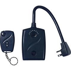
To purchase, do an internet search on the key words "GE Smart Remote Plus Outdoor Outlet Receiver" OR
Click this link for a Google search on this product: http://www.google.com/search?hl=en&q=GE+Smart+Remote+Plus+Outdoor+Outlet+Receiver&aq=f&oq=&aqi=
One minor modification I've made to my key-fob remote was to pull the internal antenna out and heat shrink it. This gives much better range and allows me to have the base in the house and me be anywhere outside in the yard and it work reliably every time.
|
||||
____________________________________________________________________________________________________________________
Charging the engine's Protosound 2 on-board battery (Applies only to PS2, not PS3 engines.) (Note: PS3 eliminates the on-board battery pack that needs charging)
You have three options:
Charge the battery on the track: Place the engine on the track, apply power to the track and hit the 'Start-up button'.
(Note: Not hitting startup results in a very very slow trickle charge which barely charges the battery.)
Charge the battery with external charger: Purchase Protosound 2.0 Battery Charger (#50-1019) and plug it into the engines battery recharge port.
REMEMBER: Remove the engine from the track and do not apply any power to the power pick-ups.
Replace the battery with a capacitor pack so you never have to recharge or replace the battery again.
Mike's Train House MTH DCS Protosound 2 Protosound 3
____________________________________________________________________________________________________________________
Triggering the Bell and Whistle when running your engines under variable throttle power only
You can trigger an engine's bell and whistle even if you're running the engine under variable throttle power from the power supply. Start your engine running under the analog power, then connect your TIU to the track in Passive mode (connect the Fixed 1 Output ports to the track, red term to + rail and black term to - rail). Then select the engine on the remote and use the whistle and bell buttons as normal.
Mike's Train House MTH DCS Protosound 2 Protosound 3
____________________________________________________________________________________________________________________
IV. AIU items:
Power and
Control powered remote switch machines:
To control a 2 wire switch machine (like Aristocraft or LGB use in G scale) with the MTH AIU requires a couple of extra components to get working. The AIU is designed to control 3 wire switch machines as is used in O and HO gauge.
Control 2 and 3 wire powered switch machine with AC power and diodes:
To control a switch with AC power you will need two rectifier diodes and an AC power supply. (AC power supply can be from 12-18v and will want it to be between 1 to 2 amps.)
(I have AC power supplies and diodes available for purchase if you need them.)
See these diagrams on generally how to wire:
Switches that utilize 2 contacts:
Switches that utilize 3 contacts (version 1): (Example: Atlas HO switch machine)
Note: Depending on the mfg, where each wire goes to switch machine may vary (and may or may not need diodes)
-v1.jpg)
Here is a photo the setup on an Aristocraft switch machine: (Note I have red jumper wires from each IN port to simplify wiring for additional switches)
|
|
|||||
Diodes will look like this:
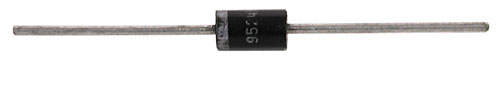
The two white wires are from the AC power supply. One wire goes to one side of the Aristocraft switch motor and the other goes to "IN" slot(s) on the AIU port. It does not matter which of the two wires is connected to the AIU and switch motor.
Next you will need to solder one end of two rectifier diodes together with the other ends facing the same direction for insertion into the AIU. (Solder the diodes in opposite directions, one with the white line on the diode closest to you and the other being furthest away. Then solder the now common soldered end of the diodes to a single wire and run that to the other side of the switch motor as shown.
Ensure the power supply is plugged in and you now have the switch machine ready to go.
Lastly, you will then need to use your DCS remote to add that switch port as a selectable switch. Once added you can then use the straight and switched buttons to control the switch.
To simplify the install of several switch machines, you can also do the following:
- Run one wire from the AC power supply to the first AIU "IN" port and then run jumper wires from the first "IN" port to the second "IN". I then repeated this for the number of switch machines I planned to add.
- Next run the other wire from the AC power supply directly outside and then split it out from there to run to one side of each of the switch machines that you plan to power. (This will save you from having to run a dedicated power wire from inside the house to each switch machine.)
- Next run a wire from each pair of diodes outside to the designated switch machines.
- To simply swapping out AIUs or moving the AIU, you can use a multi pin connector as shown below.
Parts list:
Here is a list of parts you can use to accomplish this:
Powered switch machine (like the Aristocraft ART-11299, LGB, or other)
AC power supply: Use 12v-18v (higher 18v preferred) and try and get one capable of at least 1 amp output (i.e. 20VA or higher).
Rectifier diodes: (*Click here to buy*)
Diode will look like this:
Wire: Use 20, 22 or 24 gauge stranded wire
Control USA Trains Powered Switch machine with AC power and diodes:
**UNDER CONSTRUCTION**
Mike's Train House MTH DCS Protosound 2 Protosound 3
____________________________________________________________________________________________________________________
V. DCS Software - (How to upgrade you TIU and Remote software):
TIU and
Remote software update:
The TIU (Track Interface Unit) and remote both have software loaded to them that allows them to operate and is what provides you the menus and functionality to control your trains. From time to time MTH will release updated software to enhance features or correct certain issues that may have been discovered.
1) CHECK LIST - To perform the update you will need:
Computer / Laptop - (running Microsoft Windows 10 / 8.1 / 8 / 7, Vista, XP, ME, Windows 2000, Win 98):
Download and Install the latest DCS Loader program on your computer: (See Section V at the top of this page or visit www.protosound2.com)
Cable to connect TIU to Computer: (You will need either USB cable OR 9-pin serial cable OR USB to Serial adapter cable)
USB cable: (Male Type A/Male Type B) - (Used with Rev L or newer TIU only) Can be used instead of the 9-pin serial cable. (Click here to purchase this cable)
USB port on TIU on available on Rev L or newer TIUs.
USB port now provides the internal power to perform firmware updates for TIU & Remote and updates for engine sound files. (Track power is still needed for engine)
9-pin serial cable: (Male / Female) (Click here to purchase this cable)
(*Do not use a 'null modem cable'*)
USB to Serial cable: (Click here to purchase this cable) (Use this cable if your computer does not have 9pin serial port but you have older TIU with no USB port or want to just use serial port on TIU)
**This can be used in place of the 9-pin serial cable if your computer does not have a 9pin serial port.**
Remote Tether cable: (Click here to purchase this cable)
3.5mm (male/male) stereo audio cable: (Click here to purchase this cable)
Download latest DCS software version for the TIU and Remote: (See Section V at the top of this page or visit www.protosound2.com )
2) Photos:
|
|
|
|
|
|
|
|
|
|
|
|
|
||
3) Instructional video on how to use DCS Loader (v2.00) - (*Click this link*) - (Can also view by visiting www.protosound2.com and clicking the "New DCS Loader Released - September 3, 2008)
Step 1: Updating the TIU
**When updating to a different version of DCS software in your TIU and remote, you should always start by updating the TIU first.**
Connect your TIU to the computer using either the 9 pin serial or USB cable (Your computer can already be booted up)
Plug the 3.5mm stereo audio cable ends into the TIU's "Proto-Dispatch" & "Proto-cast" ports
Connect the power supply to the Fixed 1 input port OR connect the Aux power supply to the Aux power port on the TIU
Start the DCS Loader program
Close out of any unnecessary programs or applications and do not use the computer while the update is in progress
Click the load software to TIU Icon
Carefully follow the instructions on the screen. (it will instruct you to connect the serial cable and 3.5mm audio cables)
Then select the "*.DCSt" (example: "tiu6p10.Dcst") file
The update process should start and will tell you when you are finished
TIU update troubleshooting:
If you have problems with your PC detecting the TIU:
Try using the Serial port on your computer (If you are using the USB port)
Try using the USB port on the TIU (if you have Rev L TIU or newer)
Set the bit rate for the COM port to 4800 from the default of 9600.
Go to: CONTROL PANEL -> DEVICE MANAGER -> PORTS -> Right click on the Com port being used and look for the port speed settings and lower to 4800 from 9600.
Step 2: Updating the Remote
Once you have updated the TIU software to the version you are wanting to use, then update the remote.
Connect your TIU to the computer using either the 9 pin serial or USB cable (Your computer can already be booted up)
BE SURE TO REMOVE the 3.5mm stereo audio cable ends from the TIU's "Proto-Dispatch" & "Proto-cast" ports
Connect the power supply to the Fixed 1 input port OR connect the Aux power supply to the Aux power port on the TIU
Start the DCS Loader 5.xx program
Close out of any unnecessary programs or applications and do not use the computer while the update is in progress
Ensure your remote has good batteries and test it by turning it on.
Ensure the remote is off before you get started
Connect the remote to the TIU with the 4-pin narrow phone cable. (Be sure to plug the remote into the Remote input port NOT the AIU port!!!)
Click the load software to Remote Icon
Carefully follow the instructions on the screen. (it will instruct you to connect the serial cable and remote cord)
NOTE: When instructed to press the power button on the remote, the remote should remain off. If the remote powers up, it's not detecting it's plugged into the TIU.
See below steps for troubleshooting.
Then select the "*.DCSr" (example: "remote6p10.Dcsr") file
Follow the instructions on the screen
The update process should start and will tell you when you are finished.
Remote update troubleshooting: (If the TIU is not being detected see TIU update troubleshooting above)
I. Press power button loop:
If you get into a 'loop' where the DCS Loader program tells you to press the power button, then release, then press, then release try the following steps.
1) Unplug the remote from the TIU and make sure it will turn on
2) Make sure you have good batteries. If in doubt, put new ones in.
3) Ensure the remote can detect that it's plugged into the TIU (i.e. Tethered to the TIU)
- Unplug the remote from the TIU
- Power up the remote
- Plug the Remote back into the TIU and wait 3-5 seconds
- With an engine selected on the initial screen, press the power button once. You should get a (T) displayed on the remote.
(Note: The power supply to TIU can either be on or off.) If you get a (T) displayed on the remote, retry the remote update process.
(Note: You can get rid of the (T) by unplugging from the TIU, wait 3-5 seconds and press the remote power button again.)
- *Click this link for example with (T) on remote* - indicating remote IS tethered to TIU
- *Click this link for example without (T) on remote* - indicating remote IS NOT tethered to TIU
- If the remote does not display the (T) then:
- Power down the TIU and remote
- Unplug everything from the TIU (power cable, remote tether cable, Serial cable, etc)
and let sit for 1 minute or longer and retry the remote update process.
- If you still have problems:
- Check the cable and ensure it is good. Try another cable or test the existing one with a voltmeter and test for pin continuity.
Also ensure it is wired correctly. See the information for the 4pin connector in the "CHECK LIST" section above.
- Check the pins in the TIU and Remote phone jack sockets to ensure they aren't bent or damaged.
- Try another Remote or TIU
- If all this fails, feel free to contact me, your local MTH Authorized dealer or MTH directly @ (410)381-2580 for assistance.
Mike's Train House MTH DCS Protosound 2 Protosound 3
____________________________________________________________________________________________________________________
Read about additional modifications, repairs and tips on MTH engines at the link below.
![]() Garden Railroad Modification, Repair & Maintenance
Garden Railroad Modification, Repair & Maintenance
____________________________________________________________________________________________________________________
Return to the Garden Railroad Modifications page.
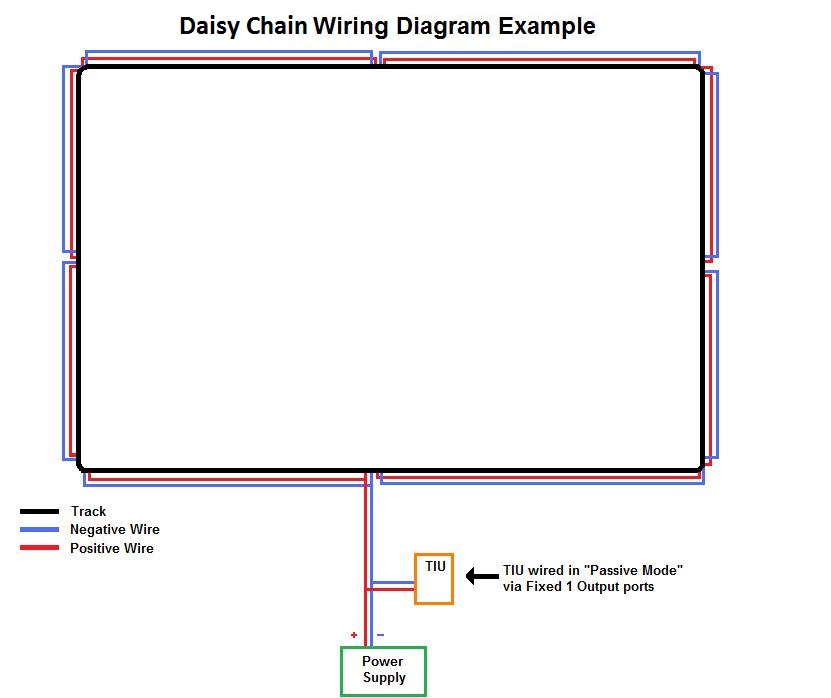
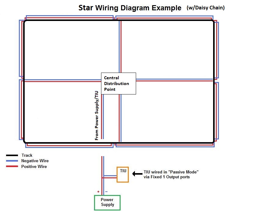
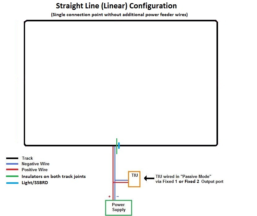
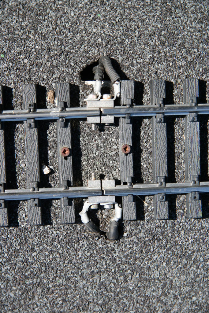
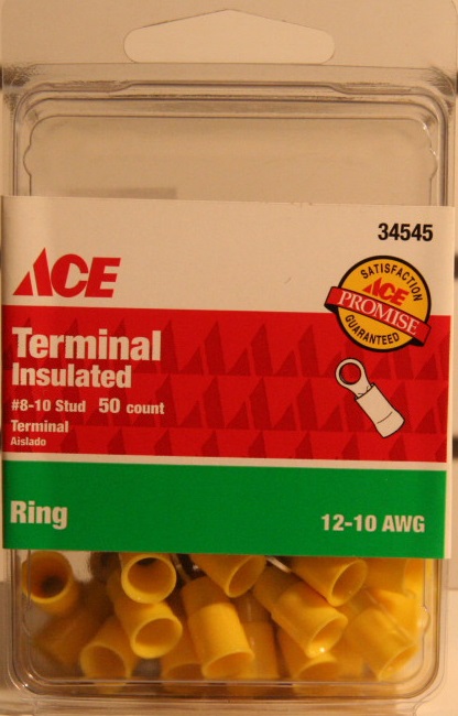

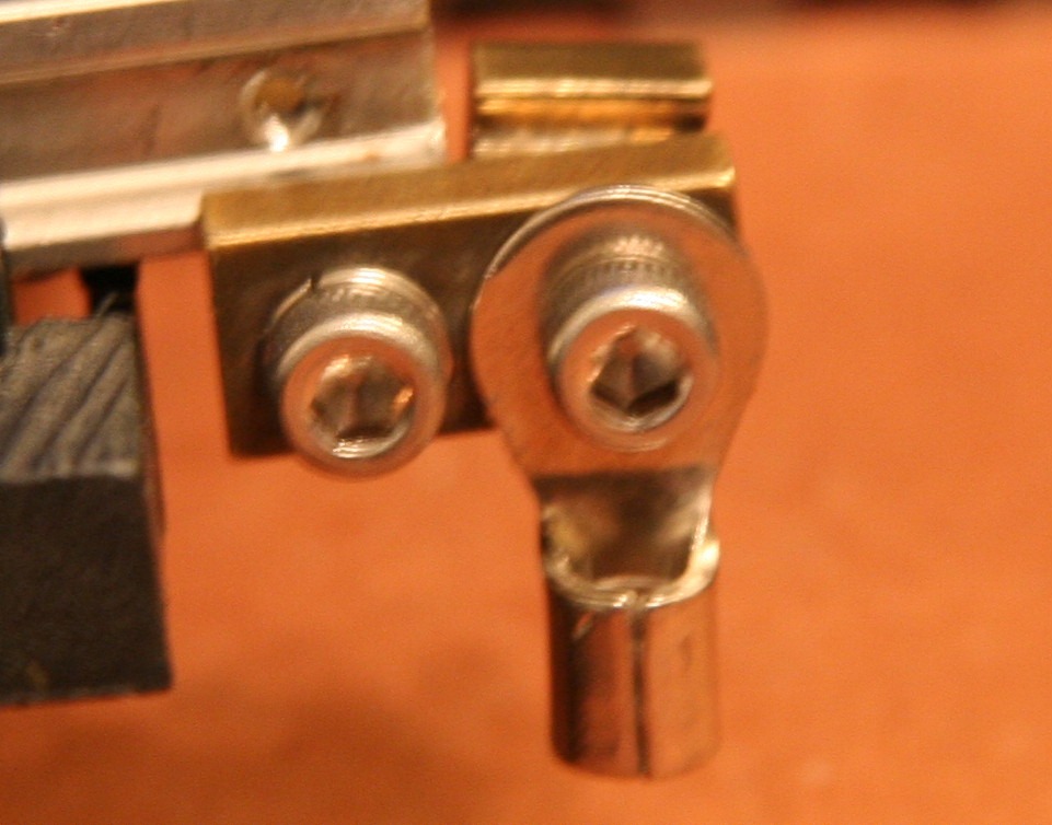
.jpg)

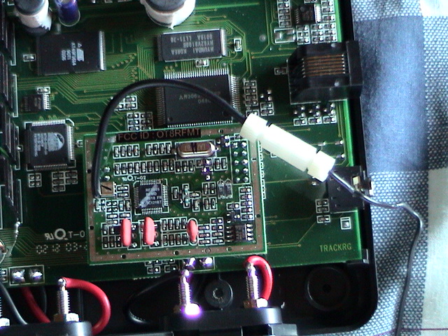
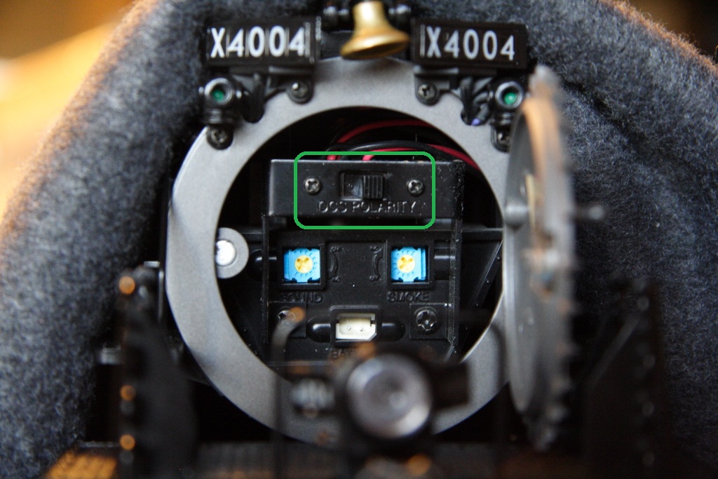
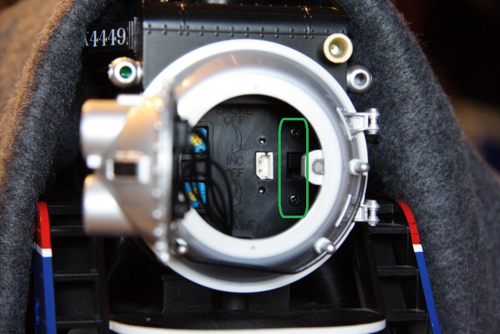


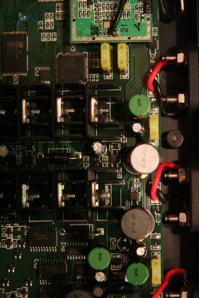

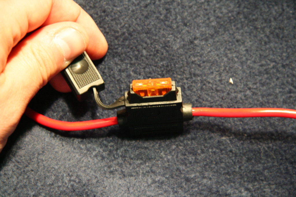

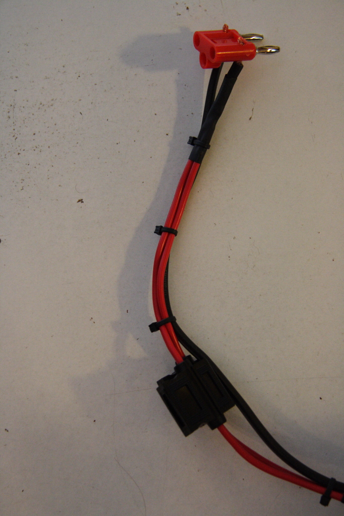

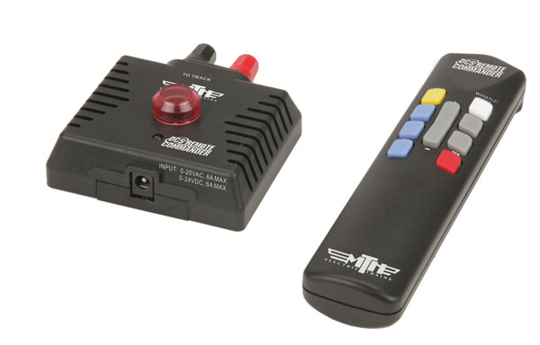
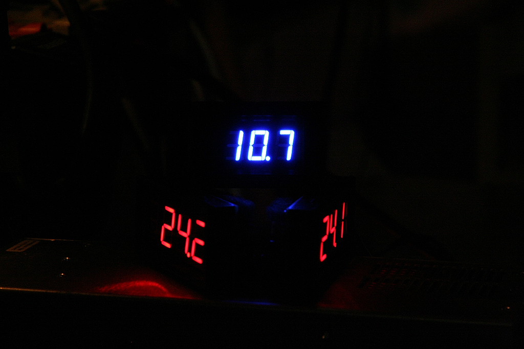
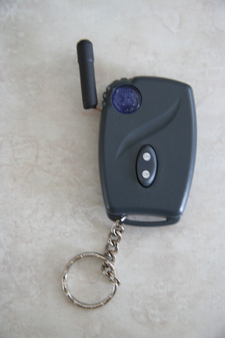
.jpg)
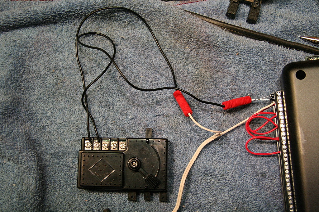


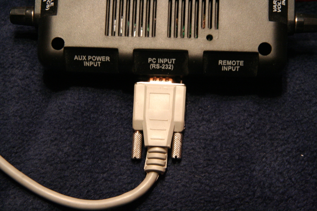
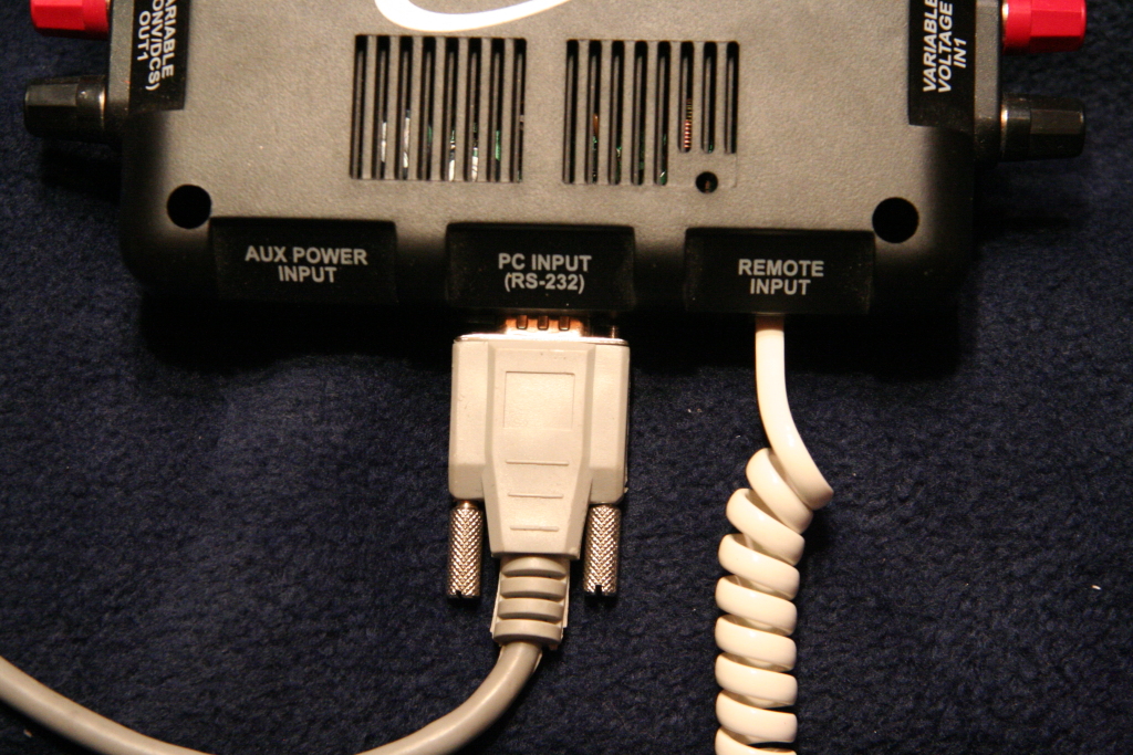
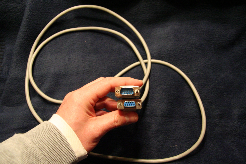


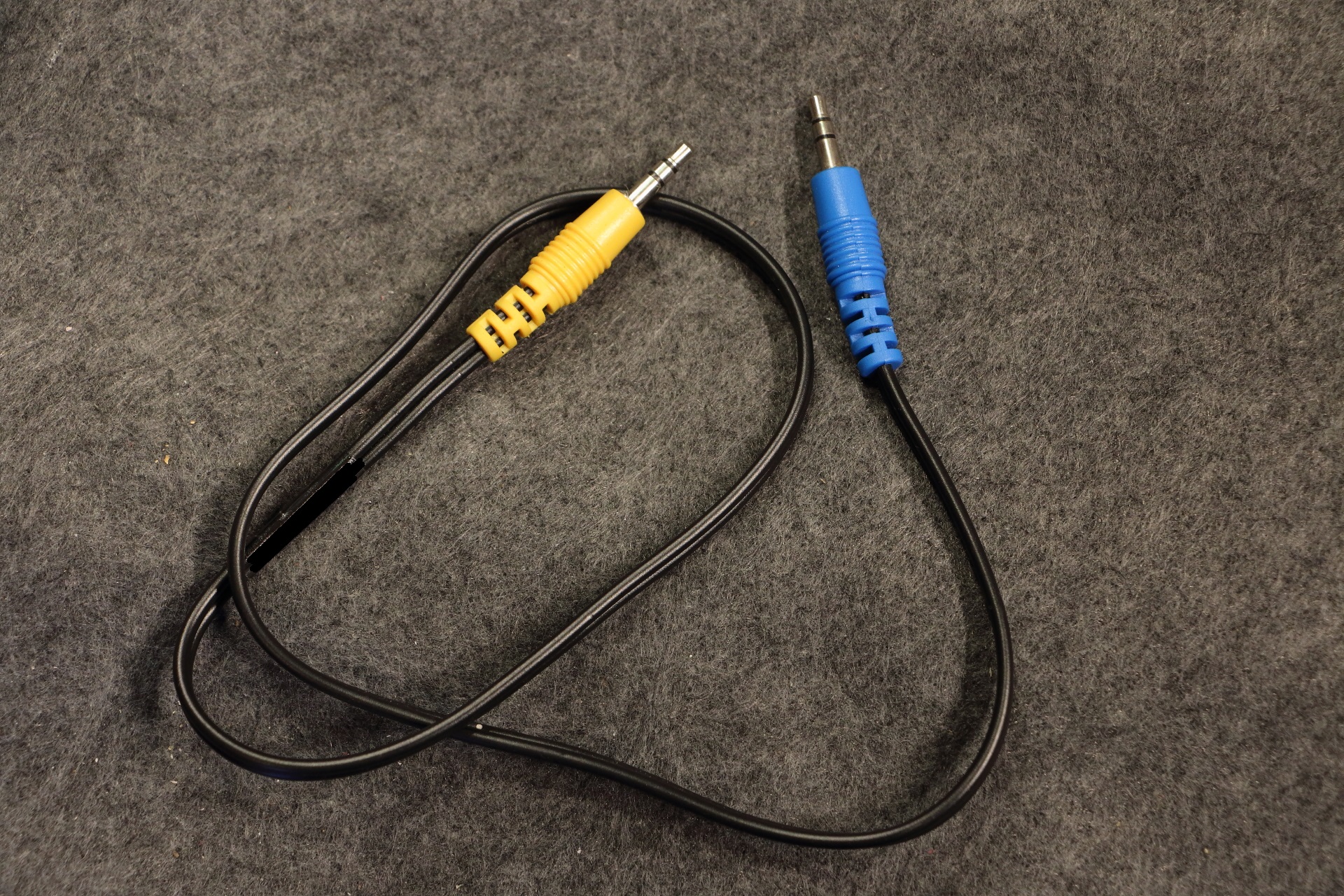
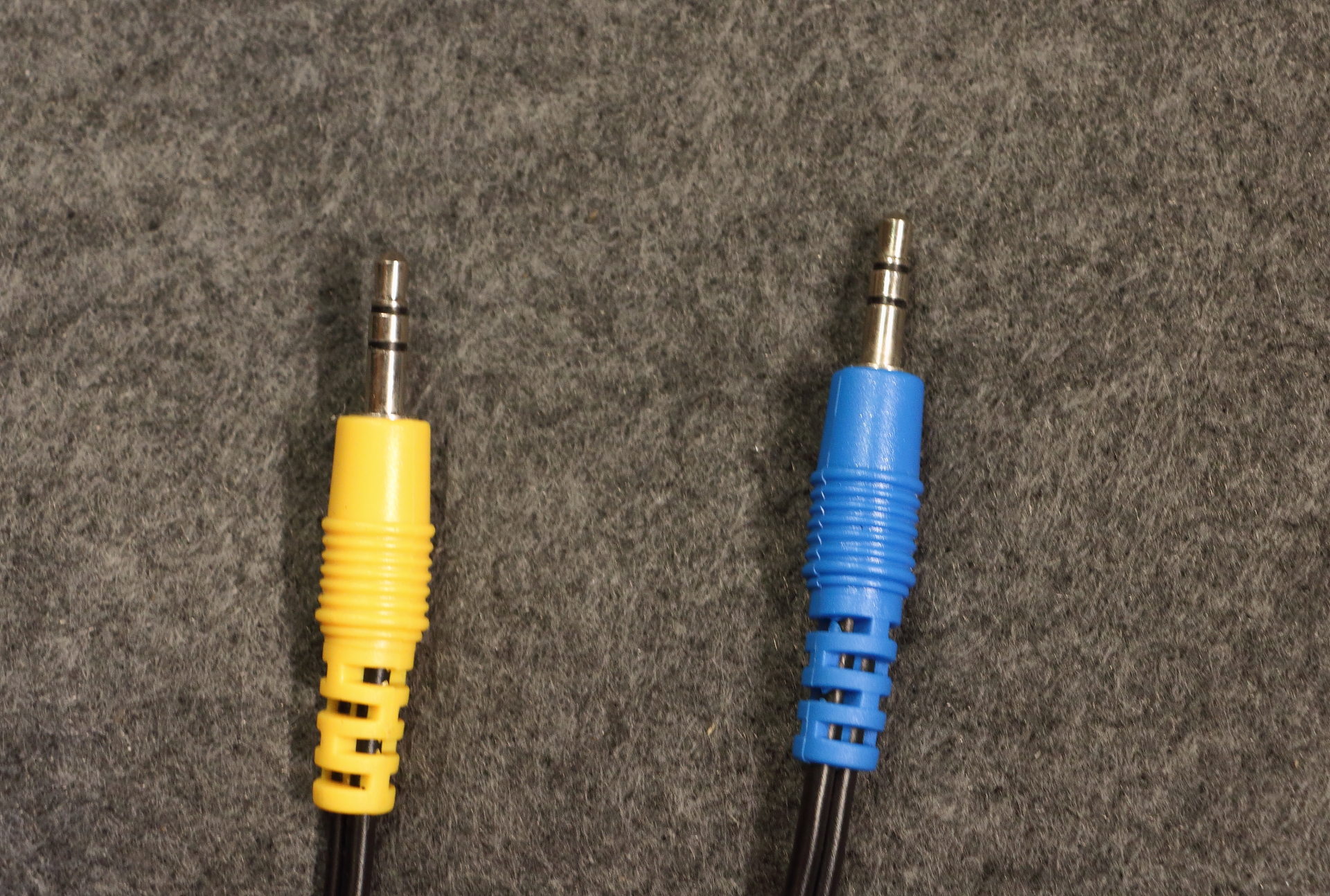

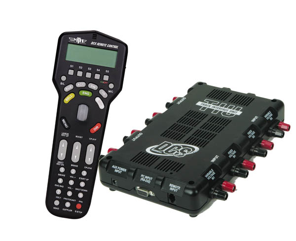
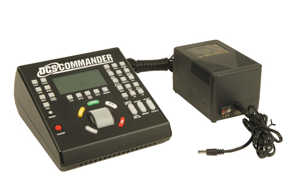
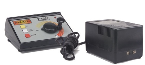
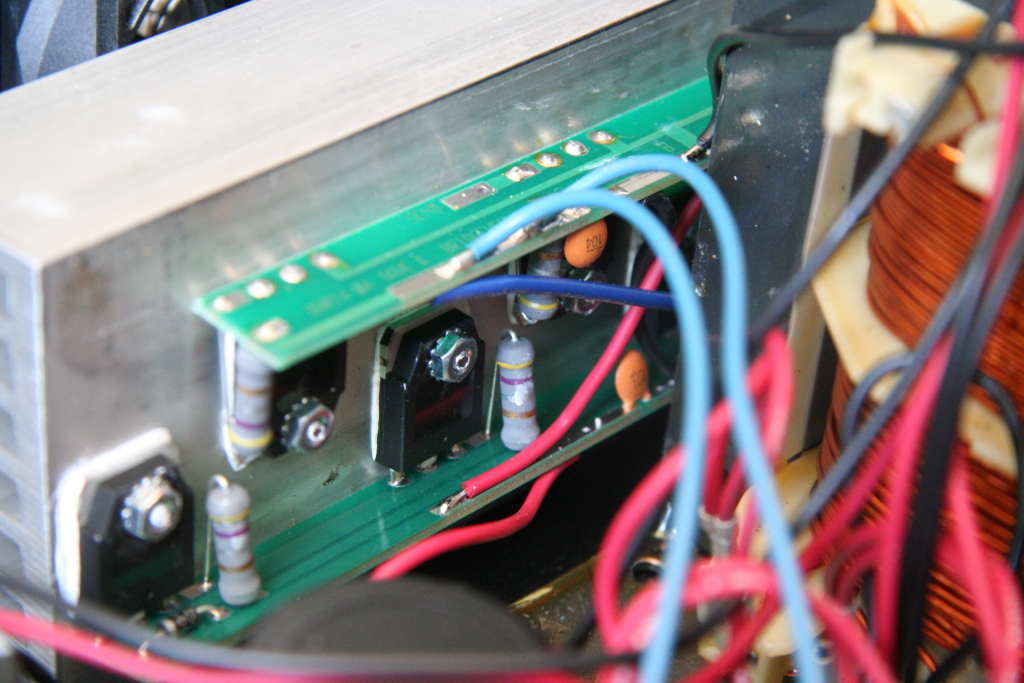
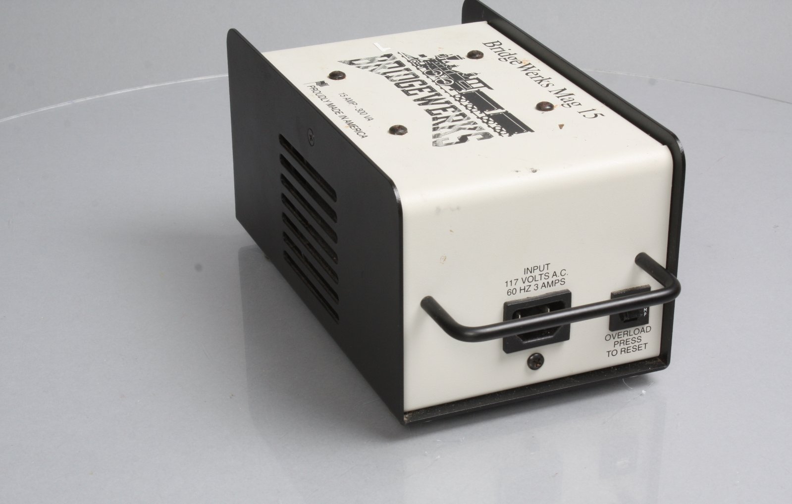
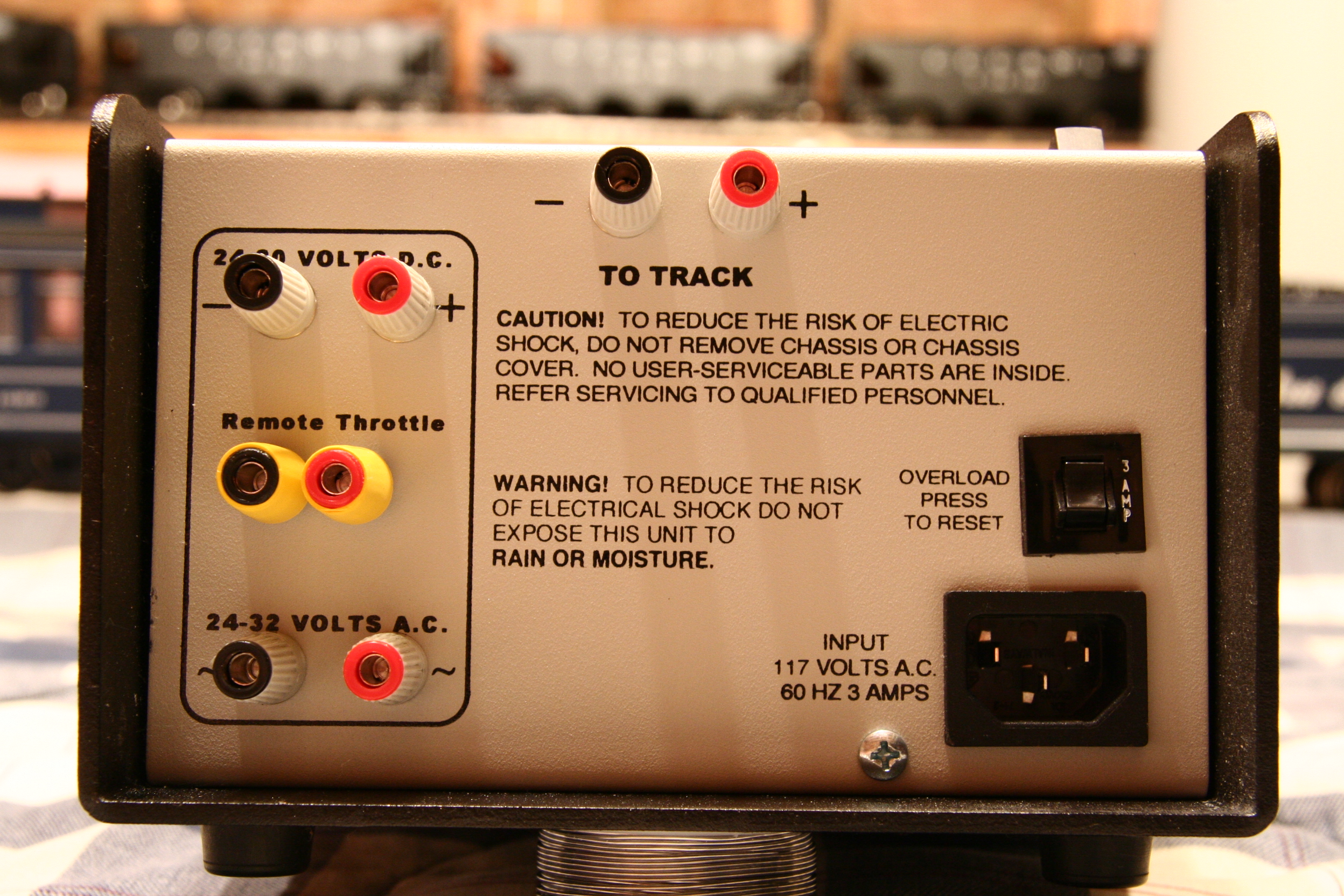
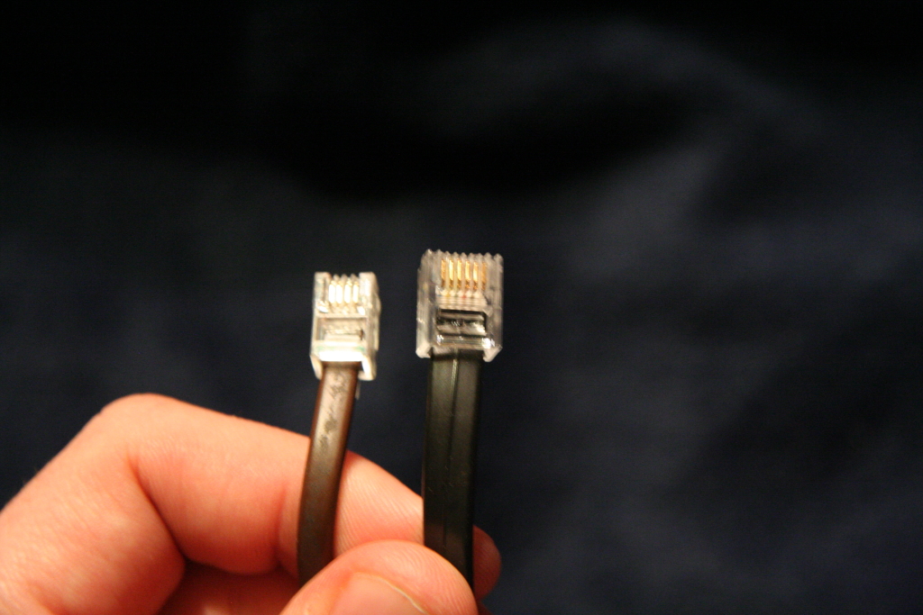
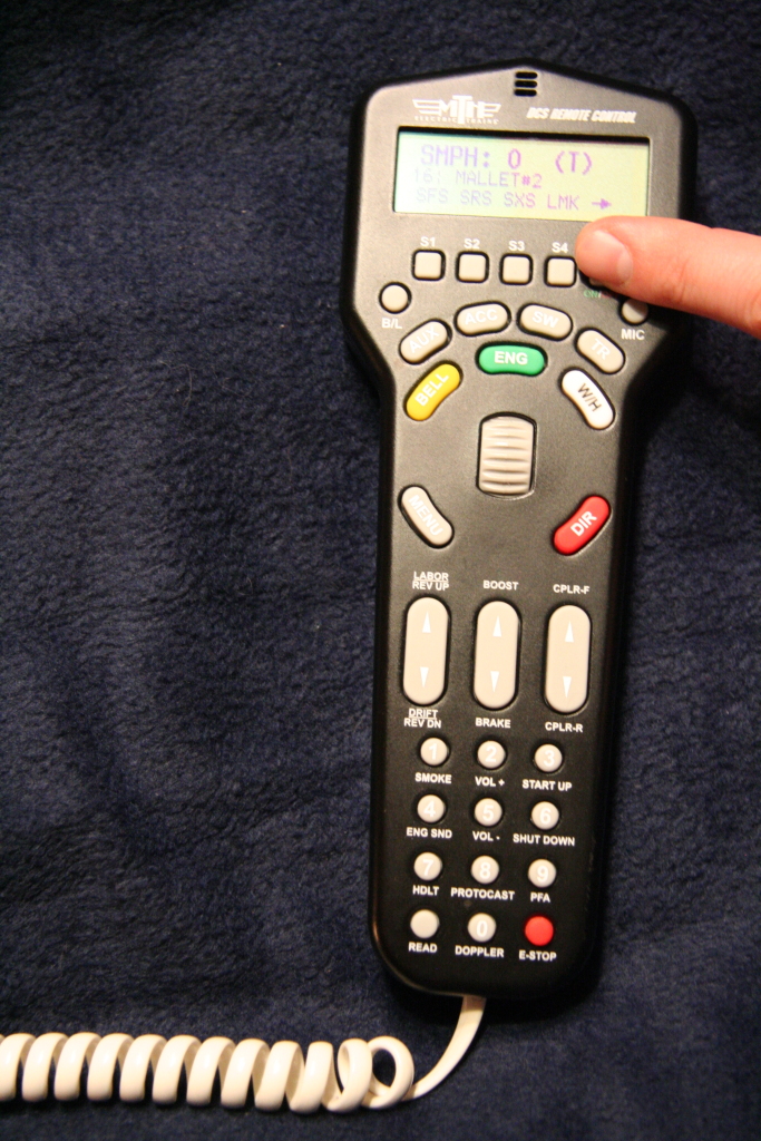
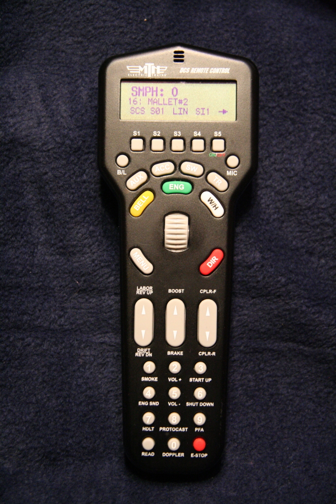